@frankly2 : My pleasure, I am glad you find it useful, though I admit, incomplete.
When I first started exploring this site, and also the vintage lathes sites on the internet, there was plenty of historical information, catalogs, books, etc. but nowhere was a set of South Bend drawings with dimensions. I even got the question "Why would you need to know"? I take apart stuff to a fault, and it rarely goes together again without something of me in it. Anything I find now gets posted here, and if, along with what members post over time, makes HM the the only place where most South Bend "down to the nuts" detail can be found, that's OK.
The "Lathe Tooling Dimensions_7324" copied PDF page has the major dimensions table for South Bend models from 9" through 16". These are nominal, and change by a few thousandths by the time the planed and scraped bits go together. eg. It's handy to know from dimension "A" that the axis of a SB9 is 3+19/32" above the cross slide plane.
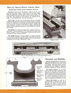
The things I found interesting were on the JPG page showing the bed section. Here is where I find out about the metal composition, 50% grey cast iron + 50% steel, from which, I suppose, one can figure the proportions of iron, carbon, and silicon. Significantly, the description for "
The Saddle V-ways" says they are "hand-scraped to conform with the V-Ways of the lathe bed". This is a scraping "straight
up", and contrasts with the explanation from Connelly's "
Machine Tool Reconditioning", where the way to go, if possible, is scraping "straight
down", unless the bed is twisted, for which he has an alternative procedure. His tricks use the scraped compound and cross-slide as template tools, to finally scrape the bed. This, I suppose, is a difference between what is done for manufacture, and what is done to re-condition.
Having not learned anything about how, I have no intention of getting into a tangle with scraping anything on my machines right now, but I may be bounced into it sooner than expected because of my current adventures with the SB9C compound. To weld it with ENiFe-C (55% nickel) while it is heated to 300C, and then have it slow cool might well leave it "changed" a bit. I have to measure first, then do the evil deeds, then measure after, and possibly have to attempt my first scraping.
Other things I have in mind are larger dial conversions, carriage stop with indicator mount, the longer travel quill goodie on the back of the tailstock, lead-screw threading indicator, and controlled drip rate oilers for the underneath drive countershaft. I already have the needle bearing replacement for the red fibre washer by the spindle back gear nut. How far I get with all this - we shall see
")