- Joined
- Jul 16, 2020
- Messages
- 27
I’m here to learn.
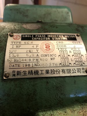
Something in my 40 yr old Chinese single capacitor motor went cactus wompus on me and started to may a metalic grinding noise.
I went to a "specialist " shop and wanted a motor to replace this one as I was told it obviously wasn’t worth even looking at.
Long Story short.
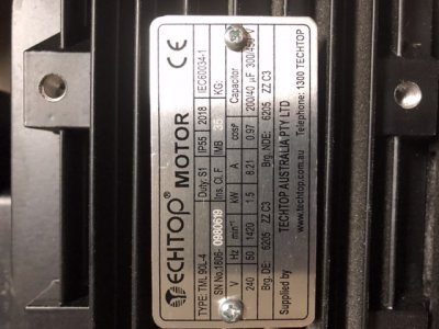
I have ended up with a run /start capacitor motor I;e two capactor motor Generic type nothing special r1 motor (well it is but common).
it is a 1.5 kw motor compared to the 1hp old one.
I was told I should be able to wire it up like the old one no problems.
After hacking away with a grinder at the universal flange and recutting The keyway and fitting the pulley.
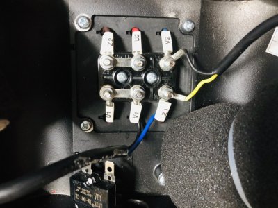
I thought I’d wire it up before trying to fit it in situation for the final clean up.
Can’t be too hard. Just like the old girl.
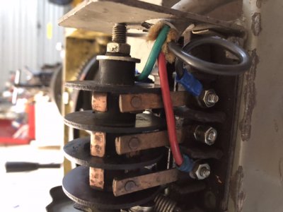
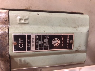
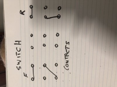
The switch I have swaps the neutral around on the old motor to make it spin backwards.
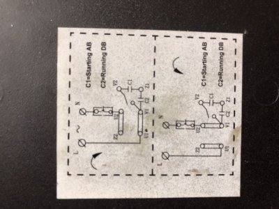
Ohh two capacitors what do they do?
I got onto to The inter web and it seems it could be a little above my pay grade to wire up. And I’m unsure.
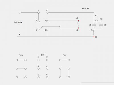
It seemed to me you could wire the reverse switch between the winding on the start or was it the run wire to make it reverse by changing the direction of the neutral or live wire and not blow the start capacitor up after bridging the motor to run the direction you want it to.
anyhoo.
Can it be done like that?
Can it be done at all without a board full of gizmo’s
Can It be done at all?
I’m only asking to find out if I’m being royally *****d over or not.
I do not know where else I could ask about such things.
I ran the wonderfull place in question and they said he didn’t know How to wire it up
I am led to believe their is someone else who is an expert who runs the place that comes and goes every now and again ....but it my be just *******t at best anyway.
Thnx
I feel I should go stick it up their arse and burn their ******* place down
But I just want to get my lathe going Honestly.


