Rotary "DRO" repair ideas

WobblyHand

H-M Supporter - Diamond Member
H-M Lifetime Diamond Member
Joined
Dec 18, 2019
Messages
6,447
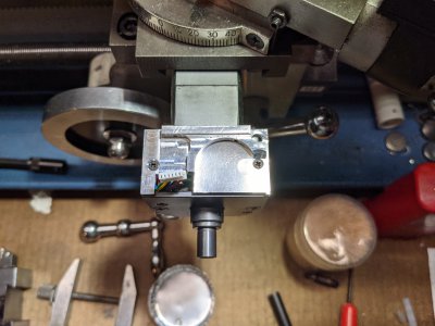
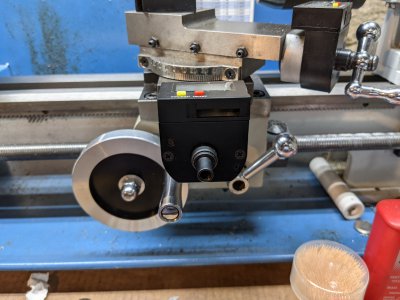
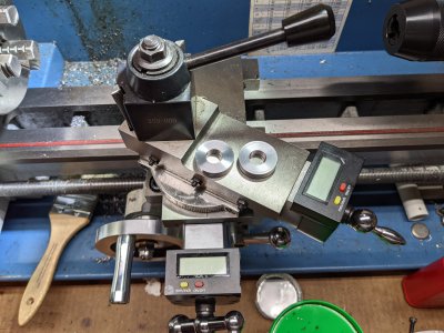
Due to some clumsiness and inattentiveness about 6 months ago (while setting up to single point thread) I managed to damage a rotary DRO on my mini-lathe. It still works, but won't tighten down properly. The display sort of pops up from the body of the unit, exposing the electronics to chips and cutting fluid. At this point the display isn't attached to the body. Obviously this is not good and I need to repair it. Trying to figure out a way to fix it. LMS is waiting for new units to come in, ie. they are out of stock and the kits have a lot of parts that I don't need to replace.

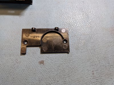
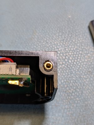
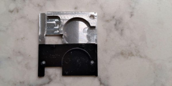
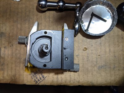
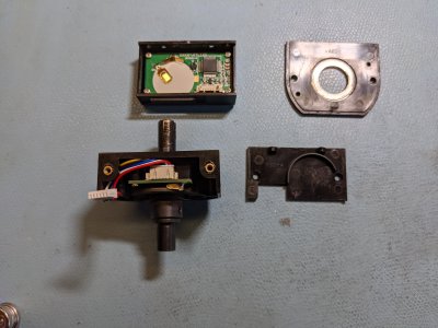
There are several things wrong. There are four parts 1) the display, the 2) display bottom plate, 3) the lower body and 4) the body cover plate. Parts 1 and 4 are mostly ok. The display bottom plate is bent and cracked near the left screw hole. When the DRO was clobbered, it pushed the right hand side brass insert in the lower body and enlarged the hole. The insert isn't captive - tightening the screw just pulls out the insert. The other insert moved, but it is still captive, at least for now. In the photo, the display is on the top left, the body cover plate the top right, the lower body is the bottom left, and the display bottom plate.

Could I epoxy the insert? Is there a better idea? Do I pull the insert then epoxy the hole and press the insert in?

I could make a fixture plate to correctly locate the holes. For that matter, I could machine a new display bottom plate out of aluminum.
PXL_20210713_194604137.jpgPXL_20210713_194818708.jpgPXL_20210713_213456370.jpgPXL_20210713_212507791.jpg
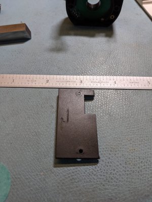
The bottom plate isn't flat anymore. There's a crack @ 2.9", right next to the hole.

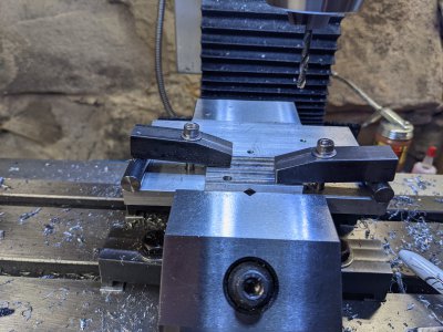
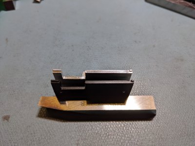
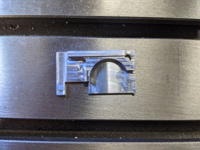
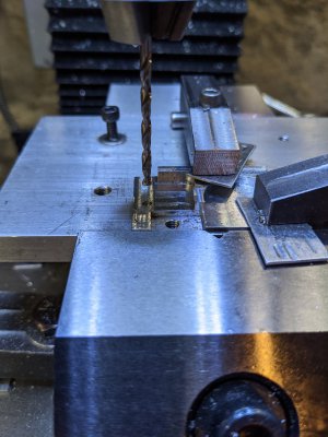
I can use the holes in the display bottom plate as hold downs. Looks like I can machine the cover out of 0.25" x 1.1" x 2" 6061. Will take a lot of operations, but it's doable. I'd use a boring head for the battery cut out (2032). The little ears on the display bottom plate need to be drilled. The original used little "wood screws" I would tap them instead, they are M2.

Any (better) ideas on how to rescue this poor thing? Thanks for any and all ideas.
 
Looks like ABS so you could use ABS cement. Epoxy would work too I'm sure
-M
For the captive nut I agree with mark, I'd just glue/epoxy it in in some way. You MIGHT consider hitting it with a soldering iron to try to 'melt' the plastic around it and re-capture it. Alternatively, if you can find a threaded insert (like for woodworking) of the same thread pitch, you could just drill the plastic and thread in the new one.

For the plate, I might just hold it flat and use the hot-paperclip trick. Basically you take a small paperclip and bend it into a shape to 'stitch' the broken plastic. Then you heat it up hot enough to melt the plastic as you press it into the plastic. It creates a strong 'stitch' there. Alternatively, more glue :)
 
Yes, the letters "ABS" on the pieces were a dead give away :D I've got some big tubes of JB Weld, so I'll try that. 24 hour cure, so I get some time to set it up right. Need to plug the inserts so no epoxy gets in the threads. Guess a toothpick would work. A little concerned about seepage permanently gluing the wrong things together. I'll try some saran wrap or something to help prevent that.

Have a little time to think about it while making a new bottom plate. The plate is 2mm thick, by the fracture, and 3.5mm from the edge, so not much to work with. Haven't had much luck repairing plastic in the past, but, maybe I can "save" the plate. Certainly given me some food for thought. ABS glue is the plastic pipe cement, right?
 
If you haven't discovered that 3m blue painter's tape it's great for those temporary gluing setups, much better than regular masking tape
Peels right off even after sitting for weeks

-M
 
If you haven't discovered that 3m blue painter's tape it's great for those temporary gluing setups, much better than regular masking tape
Peels right off even after sitting for weeks

-M
I've used the painter's tape before with cyanoacrylate. Works pretty well, although I have had it lift.. Probably should have done that this time.

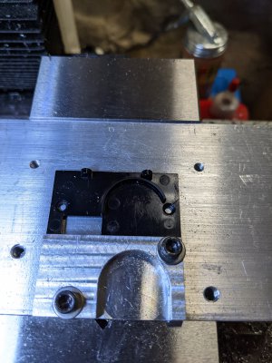
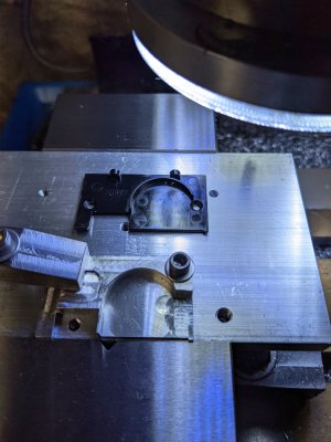
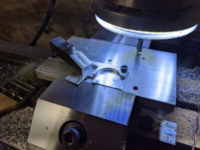
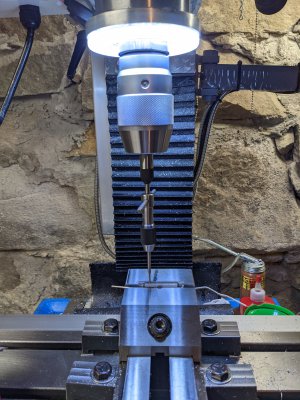
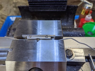
I chose to clamp the piece to a plate. Slowly carving out the piece.
PXL_20210719_202700064.jpgPXL_20210720_145156891.jpg
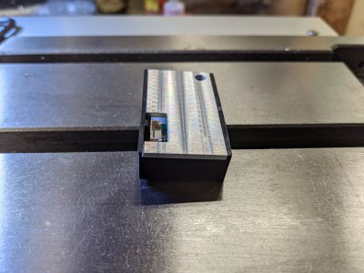
Made the clamps for this. Used the boring head to make a U-slot.
PXL_20210721_212723292.jpgPXL_20210721_222650126.jpg
image (1).jpeg
PXL_20210722_012156993.jpg
It fits in the housing now, but hits some electrical components, so it is 1mm from seating. Starting from the left side I will mill everything below the line (3mm from top edge) by 1.5mm. That should give sufficient clearance. On the bottom edge there are two tabs which are milled in. They were fun to do. They are 0.9mm wide and are used to latch into the plastic housing.

Been learning a lot doing this. Been fun figuring out the clamping necessary. Certainly haven't been efficient at it, but it is coming along.
 
So this bottom plate is done. Milled the lower part down a bit to clear some components.
PXL_20210722_134807429.jpg
Test fit in the housing. Hooray it fits.
PXL_20210722_134737985.jpg
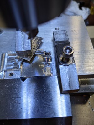
Had to do one side then the other, couldn't clamp it well enough to get it all done.
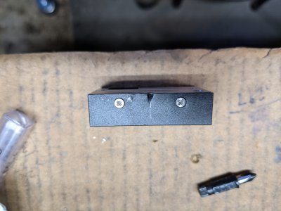
PXL_20210722_165335188.jpgPXL_20210722_172919808.jpg
Didn't have a bottoming tap in M2, and didn't want to grind what I had, so relocated the holes on the edge and drilled them all the way through with an M1.6 drill. Then while I still had the location, tapped the hole. The first one was easy. The second one was longer and filled with debris. Had to remove the tap and clean it and restart it. That's alway a nail biter, since you wonder if you really picked up the threads or you are cutting new ones. Had the tap between my fingers only twirling the body of the tap, (with no spring force) to get the feel that the tap had settled into the existing threads.
PXL_20210722_181856472.jpg
Got the tiny M2 screws in. Then another fit check.
PXL_20210722_184040627.jpgPXL_20210722_184911107.jpg
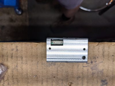
The two little holes pick up the inserts in the bottom piece. The holes I tapped even line up with the case :cool: The dark area and crease is where the compound hit the cross-slide.
PXL_20210722_184928939.jpg
Here's a picture where the assembly above mounts. The insert was loose and was pulled out with my finger nails. I need to put some epoxy on the insert, stuff it back in the hole, put some sort of release film on the plate, screw down the plate and clamp the plate. Somehow I shouldn't epoxy the threads, as I'd like to be able to get this apart again. My little clamps were just large enough to clamp this. I did a mockup of the clamping - so I wouldn't make too (too) many mistakes when doing it for real.
PXL_20210722_185425845.jpgPXL_20210722_190030344.jpg

Underneath the insert, prior to epoxy, I will put in a little piece of paper towel to catch any epoxy drops. Not sure how to keep epoxy off the M2 screw threads during assembly and clamping. Attention isn't at its peak, this afternoon, so I'll do the gluing tomorrow. Besides, it is pretty nice outside for a change and I want to get out of the dungeon!
 
Finally got back to this yesterday and epoxied the fitting. Used a piece of thin kapton tape on the aluminum to prevent any weeping epoxy from gluing the assembly together. Poked some holes through the tape for the screws. Today, 24 hours later, pulled of the clamps and was easily able to get things apart. So put everything together so I could use it.
PXL_20210727_184232812.jpg
Epoxied insert on the right.
PXL_20210727_184455678.jpg
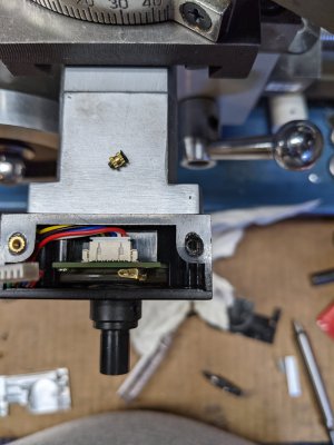
Plate screwed in place. Oops, forgot to tape up the hole on the top right! The next step it was easier to remove the unit from the cross-slide screw, so I removed the whole unit to access the tiny screws on the top edge. Stuck some kapton tape over the screw hole to prevent any bouncing chips from entering the unit. The hole faces down, so not much should get in anyways, but a piece of tape should help. Those little M2 flat head screws are hard to get in the hole. They are so short there's not much to hold on to. Fortunately the screws were magnetic and stuck to my JIS#1 bit.
PXL_20210727_185126971.jpg
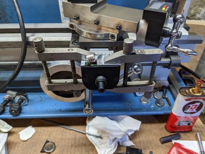
Put the assembly back on the cross-slide screw.
PXL_20210727_185407964.jpg
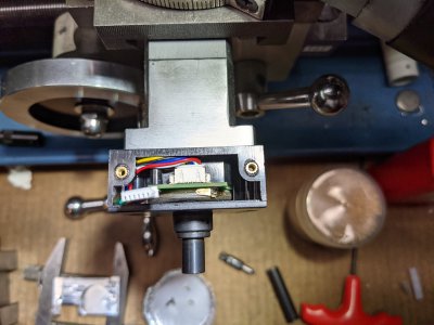
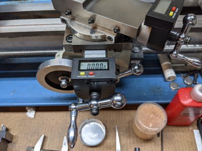
Install the battery and the handle. Woohoo, it works!
PXL_20210727_185547478.jpg
Make something to celebrate! Some 1" OD washers 0.25" thick for my mill vise. The ones that I had were flimsy.
PXL_20210727_195359945.jpg
Done. Time to crack a cold one!
 
Back
Top