- Joined
- Dec 3, 2023
- Messages
- 81
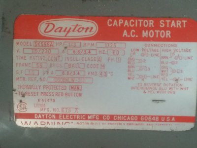
I should have started my own thread on this previously but I didn't. I hoped that I was missing something simple and it would be resolved simply, but instead, I learned that I couldn't get a simple answer to the complex wiring I was dealing with. The more I researched, the more I found my motor's wiring was not simple compared to most motor wiring schematics. I ended up needing a 20 pole switch to change spin direction and I used every terminal.
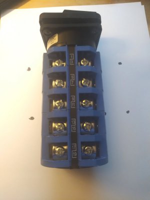
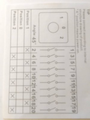
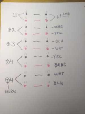
I thought about buying a new 1/3hp motor that might be easier to wire up the $15 amazon switch that I already had, but new motors were at least $160. going all the way to $300. if I wanted a certain brand. After bouncing my dilemma off of Mark in the other thread which I posted in, and following his link to a multipole switch, I realized that a switch similar to the one he suggest could do the job. I did my own pin diagram and came up with 20 poles to get every wire switched for both spin directions, and here's the result. Hopefully, it helps someone else who has the same complex wiring, or similar. The Baomain switch was $28. on amazon. It didn't come with an electrical box housing of any sort, so there's some extra work to be done.
I colored the Pin drawing in pink and black so the energized circuits would share the same colors when one or the other was switched on. The motor terminal side shows the "<" symbol which is a shared wire from each pair to the motor terminal. This works because only one wire in each pair is energized at a time depending on the switch position.
The motor is a Dayton 5k599a
The switch is a Baomain Universal Rotary Changeover Switch SZW26-63 660V 63A 3 Position 5 Phase SZW26-63/D505.5
Pictures below:


Last edited:


