- Joined
- Dec 24, 2020
- Messages
- 1,053
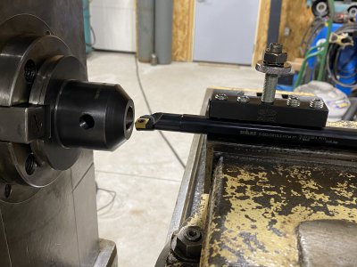
Okay, I'm not really sure what to call it, but I'm going with "reverse boring"! I want to bore out an NMTB 50 end mill holder from 7/8" to 1.25" so I can adapt it to an arbor I have that won't fit the K&T. I'd like to bore it while mounted to the mill so the hole is perfectly aligned with the spindle. My first thought was to grab a boring bar in a QCTP holder and secure that in the vise, as pictured. My concern is that downward pressure on the insert tip might cause the holder to move in the vise (the back would rise). The boring bar projects from the side of the holder enough to make solid contact along the length of the vise jaw. That should somewhat support the front and help resist movement, but no telling how much. I could change and put parallels under the QCTP holder so that the boring bar isn't making contact at all, but I'm not sure that offers any benefit since the holder could still rise up off the back of the parallels...probably a bit more support up front though.
Maybe I should just clamp the boring bar directly to the table with hold downs? I'm thinking of trying the pictured setup with light cuts, see if the boring bar/holder moves at all and if it does switch to another method like clamping it to the table.
Is there an easier/better way I'm overlooking?
For those interested, I'm making the Franken Arbor for my K&T 2H for a couple of reasons. I didn't have a 1" diameter arbor of any kind, but have a pretty good pile of 1" cutters for starters. Then I stumbled onto a really nice German made NOS 1" arbor at a local machine supply place, but it has the wrong mount (reminds me of a long Jacob's taper or similar). It's a nice length and came with a full set of spacers and two running bushings, for $50....had to buy it. I'm going to shorten and turn down the mounting end so it's 1.25" diameter and a bout 2" long so it will fit the NMTB 50 end mill holder.
Shar's finest The vise has slots on either side of the screw and I may see if there's a way I can run a bolt up from that and put a plate across the top of the boring bar and vise jaws like a makeshift hold down. Nothing is tightened down in this picture as it was just a concept to line things up...I'll tighten all four set screws when ready.

Maybe I should just clamp the boring bar directly to the table with hold downs? I'm thinking of trying the pictured setup with light cuts, see if the boring bar/holder moves at all and if it does switch to another method like clamping it to the table.
Is there an easier/better way I'm overlooking?
For those interested, I'm making the Franken Arbor for my K&T 2H for a couple of reasons. I didn't have a 1" diameter arbor of any kind, but have a pretty good pile of 1" cutters for starters. Then I stumbled onto a really nice German made NOS 1" arbor at a local machine supply place, but it has the wrong mount (reminds me of a long Jacob's taper or similar). It's a nice length and came with a full set of spacers and two running bushings, for $50....had to buy it. I'm going to shorten and turn down the mounting end so it's 1.25" diameter and a bout 2" long so it will fit the NMTB 50 end mill holder.
Shar's finest

Last edited:

