Rethinking My Approach with a VFD

I really appreciate the information. I had a thought that I might have to place the shop light switch near the lathe. That way I could turn the lights out, start the lathe, then turn the lights back on. Don’t want to overload anything you know.
When I start up my ADX30 (30HP) phase converter, it causes the lights to flicker in all the houses on my end of the street. So I don't turn it on and off all the time. Try to start it early in the morning and leave it on all day if I think I'm going to need it. Note that is just starting the phase converter itself with no load. Once it's running, starting 3ph loads doesn't cause much issue.

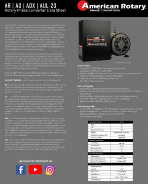
The ADX30 is a bigger phase converter than you need, but not by much. You could probably do an ADX20 if you're looking at American Rotary products.
 

Attachments

  • Screenshot_20220121-212158_Chrome.jpg
    Screenshot_20220121-212158_Chrome.jpg
    79.9 KB · Views: 11
  • Screenshot_20220121-211757_Chrome.jpg
    Screenshot_20220121-211757_Chrome.jpg
    79.6 KB · Views: 11
1.) Do I understand correctly that the VFD runs continuously. You then power the lathe with a magnetic switch and use it’s controls normally?

2.) How do you get the VFD to power up without the motor load without complaining?

3.) Tell me about this sine wave filter of which you speak?

Yes. The VFD runs continuously. I do turn it on with a circuit breaker only when I want to use it. The contactors on the lathe work normally. The output filter protects the VFD from the switching of the contactors on its output. I've been running mine for many years not this way. The three phase actually powers multiple machines, not just the lathe.

The output filter seems to make the VFD happy. My VFD is a surplus Yaskawa F-series drive.

The sine wave filter I use is made by MTE. It has a three phase inductor with capacitors. It takes the PWM "choppy" output of the VFD and makes the output look more like a sine wave. I got the filter off of Ebay.

Also, I first tried a RPC with this lathe. It has a 4HP motor so I got a 5 HP RPC. It was an absolute DOG. The lathe would start in lower gears but it spooled up slowly. In higher gears, the RPC was overloaded and the CB tripped often during start-up. I later found out that I should have used 2X the RPC size for the lathe load because of the inertia I guess.

I will look further into the things you brought up. Thanks again.
 
The sine wave filter I use is made by MTE. It has a three phase inductor with capacitors. It takes the PWM "choppy" output of the VFD and makes the output look more like a sine wave. I got the filter off of Ebay.

Not a rhetorical question or a veiled jab:
Have you looked at the output of the filter with an oscilloscope to assess just how much more "like a sine wave" it makes it? I ask because I've contemplated doing this in the past, did some tests, and saw on my scope that the output with my filter was still a far cry from "sinusoidal." I did not have a buffet of filters from which to choose the one that worked best, but with what I had, I observed different levels of effectiveness in cleaning up the power depending on load and other things. It seemed like a crap shoot to me and I did not feel comfortable subjecting sensitive electronics to that kind of supply. It would have been fine for a shop full of manual machines but I use mine to power up CNCs and industrial control panels. But if you've verified that the output is "clean" from your filter I'd like to know the specs of that filter so that I can obtain one and give it another go.

P.s. just because a VFD doesn't complain about its input doesn't mean it's a clean input. A VFD will happily run on anything from DC to probably a few kHz, with +/- xxx variation in voltage. I just powered up a 480V 3ph VFD yesterday with 120V single phase to get the parameters out of it, and it didn't even fault out. I was curious if it would actually run a motor in that state, but didn't have time to test.

Also, I first tried a RPC with this lathe. It has a 4HP motor so I got a 5 HP RPC. It was an absolute DOG. The lathe would start in lower gears but it spooled up slowly. In higher gears, the RPC was overloaded and the CB tripped often during start-up. I later found out that I should have used 2X the RPC size for the lathe load because of the inertia I guess.
Yes, the stated HP of a RPC is almost always the "running HP" and there is a separate spec for "starting HP" which is close to half. This is why I recommend a 20HP minimum RPC for this 10HP lathe.
 
Regarding "how sinewavy is it?". I have looked on the output with a scope. BTW It has to be an isolated scope channel to avoid damaging the scope. It is not bad. It is not perfect but good enough for a motor. Probably about 10-15% THD or so. I know some of the filters are just "dv/dt" filters to get rid of the sharp edges to avoid spewing EMI everywhere and reduce stress on insulation, especially in the case of long cable runs. I have a DRO on the lathe and it seems happy. I've had no trouble with that anyway. It is important to get a filter that is designed for the job. Tomorrow I'll go to the shop to find the make/model of the filter I have.

Regarding the input. I added a series inductor to the input too in order to make it easier on the building power. I didn't have too many worries as I run one machine at a time and have a separate 200A feed to the shop. I bet your 480V VFD will fault out if you put a decent load on it. The setting for the input voltage fault is adjustable. Maybe yours is set to a low voltage setpoint for the trip-out.
 
So a number of different approaches, given a big enough VFD, other individuals they have used it as a "fixed" 3 phase power source for their machines, but it is not just a factor of 2 for single phase input. You need a much larger VFD to deal with the high start up current of motors not being controlled by the VFD. You need significant filtering that it does not interfere with the control systems. Many VFD's will operate over a wide voltage range, but for the most part the output cannot be higher than the input unless you have a voltage doubler circuit. On the 200-240V VFD's they will dropout at 120VAC, have had a few people connect them up incorrectly. Nice thing on some of the newer VFDs is they will program off of the USB power when connected to a computer.

I see no reason to need to turn off the Phase Perfect when not in use, they draw less than 100W at idle, RPC many individuals have it dropout when the lights get turned off. The Phase Perfect produces full sinusoidal three-phase output voltages balanced to within <2% under all load conditions. Because the output voltage is a sinewave with low harmonic distortion, all types of three-phase equipment can be safely powered per the manufacturer. RPC is the least expensive option if you build you own, if buying a turn key system, a 20 Hp RPC (which is recommended for a 10 Hp motor) is close in price to the Phase Perfect 10Hp which will drive the same load. One would probably want to go with a 15Hp Phase Perfect so you could power more than one machine, it is also unlikely that you will be using manual machines at anything close to full load for a sustained time frame. You could also buy a RPC box for not much and find a 20 Hp idler. If you want to run a VFD off of an RPC, I recommend going up one size in capacity, there is a small derating when running them off of an RPC.
 
mksj - Do you know a rule-of thumb for sizing a VFD as a static converter? I think you are right about needing to oversize due to start-up currents but I assume it depends on the design of the VFD as to what factor is needed, one designed close to the bleeding edge vs. a more industrial VFD.

TNBEN60 - I had a look. The filter I use (surplus from EBAY) is an MTE SWAGA0030D. mksj makes good points. Using a VFD as a static converter takes oversizing. Since I'm in it partly for the adventure and I got the big VFD very cheap, it worked for me.
 
Last edited:
To add to the above, when I purchased my Deckel CNC, I was instructed that the Phase Perfect was the only way to power it off of my residential single phase . Why, because the Phase perfect was the "perfect 3 phase generator". It has really good balance between phases and is very clean power. You might ask why spend all that money one of these and not go with another means of obtaining 3 phase. Because when the old German CNC circuit boards are $2-3K per board at the time and there are multiples of these in the refrigerator sized control cabinet, I didn't want to take chance with bad power. I ran the Phase Perfect for over many years and when I moved into my new "Man Cave", which had 3 phase power, I sold the Phase Perfect close my purchase price,(high resell).
 
Last edited:
I have only dealt with smaller VFD installs, mostly 5Hp and under, and not my background which is medicine. Where I have read others using the VFD as a fixed 3 phase power source, it has been older installs using much larger older style VFD's (surplus-cheap) and old style manual machines (not for CNC/electronics). If you figure that the startup draw of a motor is quite high like 8X the FLA, a VFD can provide probably 2-3X, and then factor in derating for single phase 2X. You are probably need 6-8X the the motor FLA for the VFD output, it would need to run in straight V/Hz, might be issues with THD which would trip it into an error mode. Larger VFD's usually have DC chokes which would be required, and then you would need some form of output filtering sized for the peak currents.... Discussions on it have mostly been over at the Practical Machinist, and more from years past, I have not seen it recommended as a general practice. You also would need a sizable service to the VFD, minimum would be 125% of the rated input, not what it is driving. I cannot see it as a practical solution these days, when an RPC can be done for very little.

Phase Perfect is what I see most people use if they have any type of electronics in their control system, or as a simple three phase power source for single phase input. Given the high efficiency and low standby power dissipation the service requirement would be much less than an oversized VFD. They appear to be reliable, and some of the previous issues seem to have been addressed with the newer models. Only issue that I recall reported from a reliability standpoint is the capacitors have a rated life and need to be replaced at regular intervals (years).
 
I am adding a new to me lathe in my shop. Its a Mazak with a 10 HP, 3 phase motor. I have used static phase converters, rotary phase converters and VFD’s in the past. I really like the utility of a VFD. But, when the electrical panel looks like this I question the viability of inserting the VFD so that it is directly connected to the motor. I also wonder about my ability to get in and out of 40 year old wiring without causing additional problems. This may just be a case where a rotary phase converter is the better option. I’m going to ponder on it over the weekend and was curious if anyone else had thought through this before.
Is this a CNC mazak???? Where are the drives and existing spindle VFD.
 
Back
Top