- Joined
- Aug 14, 2011
- Messages
- 101
I own a Grizzly G3368 mill/drill which has seen a considerable service during the four years that I have owned it. The G3368, like most Chinese mill/drills mine uses a cast iron lead screw nut. Cast iron is only suitable in this role for light duty usage. Over time the backlash has increased to 0010-0.015”. Some of this backlash is due to play in the bearing assembly which has no preload, the rest is due to wear of the nut and the screw. I believe this is a fairly typical situation for this type of equipment with four years of regular use. I explored the various options on how to repair this problem and have decided that first a new lead screw is needed since the cast iron nut has worn the lead screw in the center portion where most of the use is. And second, the bearing assembly needs to be properly installed with preload so that this does not become a source of backlash in the future.
The following article describes the steps that I took to repair this specific mill but since much of this equipment is very similar others may find my experience with this project beneficial.
Where to start?
In order to have a smooth and uniform running lead screw, alignment is everything so the first step after removing the table is to measure things. Specifically the height of the screw above the base, diameter of the existing screw, position of the end cap shaft holes relative to the center of the existing nut, etc. A more subjective set of dimensions have to do with how much room is available for the new nut. I plan to use acetal plastic for the nut (more on that in a minute) which will require a metal housing to support and locate the new nut. The size of the housing will be somewhat larger than the original nut so an accurate estimate of the size is important.
From these dimensions I derived the location of the new screw center, the diameter of the nut, screw diameter, and the size of the housing that will hold the nut. Once I had this information I was ready to start fabrication. Diagrams 1 through 4 show the dimensions I ended up with.
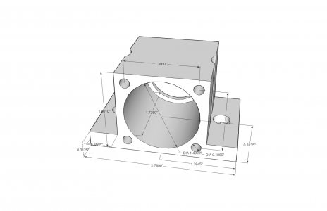
Diagram #1 - Acetal nut housing.
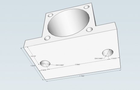
Diagram #2 - Bottom view of nut housing.
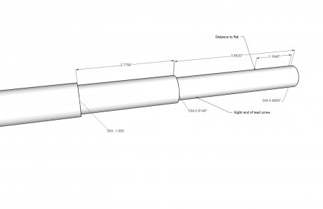
Diagram #3 - Right end of lead screw.
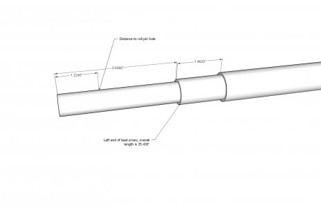
Diagram #4 - Left end of lead screw.
Why acetal plastic?
The replacement nut for this project is made from acetal plastic (Delrin). I have used this approach previously with excellent results. I documented a previous project on using acetal to fabricate the lead screw nut for the G0602 lathe cross slide. You can find that article here:
http://www.projectsinmetal.com/foru...-cross-slide-more-accurate-and-less-backlash/
The original source material that got me interested in using acetal was a post by Evan Williams on the HomeshopMachinist web site. You may find that article here:
http://bbs.homeshopmachinist.net/threads/43645-Making-Acetal-leadscrew-nuts-the-easy-way
For the hobbyist using acetal in this application is in my opinion, the best and most viable of the options. Most hobbyists would have difficulty in doing the internal threading of cast iron or bronze which are the most common materials used. Heat forming acetal provides a near perfect set of threads. In most applications an external housing is needed to contain the nut and hold it in position. The housing must be small enough to fit within the space provided in your equipment but this is usually not a problem. Once the dimensions of the housing is determined and the housing is machined then the external portion of the nut is machined to fit the housing. A threading chase is made and the nut is run on and off the chase to loosen the threads. Overall, not a complicated process and the results are excellent.
Replacing the G3368 lead screw and nut.
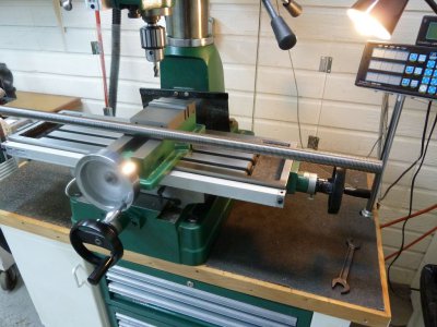
Photo #1 – The new lead screw on the mill table that will use it. The new screw 1 x 36 “ at 10 tpi. No, I do not mill with a drill chuck, I was counter boring a screw hole.
After examining the lead screw and nut on my mill it became apparent that due to the wear on the screw that I would be better off starting with a new screw. I ordered a three foot piece of 10 tpi x 1.000” acme threaded rod. The original screw was an odd diameter, 0.949” or 26.7mm with threads at 10 tpi.
The first step was to prepare the acetal blank that will become the new nut. I used a piece of 1.625” acetal rod that I purchased from Enco. The rod comes in a white (natural color) or black, I used the black. I started by cutting off a 2.000” piece in the bandsaw. Acetal is very easy to machine, I left the outside diameter at 1.625” and using the lathe drilled a 0.875” hole through the center. I finished the hole to size with a boring bar. The hole size for making a nut is the diameter of the screw less one thread depth. In this case the screw was 1.000” and a 10 tpi acme thread has a depth of 0.050” so a hole size of 0.950” was needed. Once this was achieved the blank was split by sawing using a slitting saw on the mill.
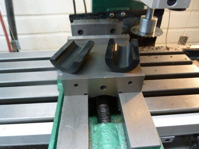
Photo #2 – Sawing the nut in half, don’t worry if both sides are not exactly half heat forming will take care of the differences.
The next step before heat forming is to mill or cut the threads of the rod to make a chase. The threading chase will be used to loosen up the heat formed threads which after forming will have zero clearance and be very hard to turn on the shaft. Since this is a right hand thread we want the cutting edge (the edge perpendicular to the axis) to present itself when threading the rod into the nut. I used the mill to cut three slots that will act as chases. You may also use a Dremel tool with a cutoff wheel. In a later step we will use this method for the final chase. I preferred the mill technique since the slot is wider and will hold a larger amount of removed material without binding. If you choose to use the Dremel tool cut five or six slots along the axis that are deep enough to pass through the threads and into the screw base. This part of the new screw will eventually be turned down and this chase will not be part of the final assembly.
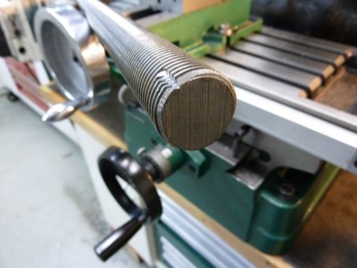
Photo #3 – The milled threading chase.
I used a bench vise to apply the pressure to form the nut, to support the nut halves I bored a hole in a piece of 4 x 4 wood and then trimmed it up in the table saw. This helps make the pressure uniform and also keeps the bench vise from becoming a large heat sink.
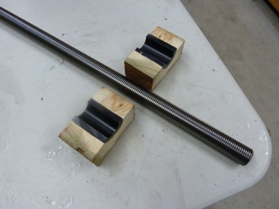
[FONT=&]Photo #4 – Blank halves in the wooden supports.
[/FONT] Since this is a relatively heavy piece of steel it needed some support else when the acetal reaches the flowing temperature the weight of the new screw will distort the nut.
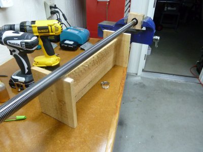
Photo #5 – Lead screw with the blank halves clamped in the vise and a wooden frame to support the shaft during forming.
Heat forming is a slow process, the idea is to slowly raise the temperature of the rod which in turn will transfer the heat to the nut halves. Acetal will begin heat form at about 250 degrees F and will melt at 338 degrees F. I used a small propane torch to heat the screw, slowly heating both sides of the nut evenly, never allow the heat source to be pointed directly on the acetal material. This should take about 10-15 minutes, if you go too fast and end up with the screw too hot this will result in melting the material, go slow. As the nut begins to form continue tightening the vise until the halves come together. Excess material will form at the ends of the nut, when this begins you are done. Let the screw cool until you can handle it without gloves. Since the screw and nut have zero clearance you will need some mechanical assistance to remove the nut from the screw.
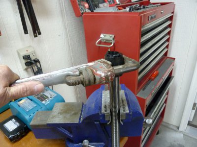
Photo #6 – Removing the nut, the pipe wrench will leave some marks but those will be machined off.
Once the nut is removed mount the screw in the lathe with the chase end exposed. I used a short piece of tubing to act as a spacer as shown in the next photo. I machined off the excess material and then began working the nut on and off the chase cleaning the chase after each cycle. This will take awhile, the acetal if pretty tough and although it machines very easily removing excess material with a chase is a slow process. On your first pass or two you will only go past two or three threads and then have to back off the nut and clean the chase. Each pass will go a little further than the previous.
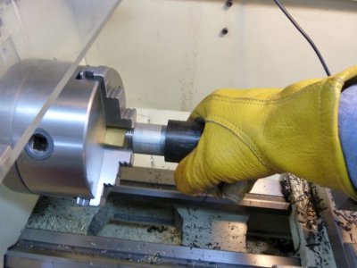
Photo #7 – Chasing the thread, you may need some mechanical tools to hold the nut for the first few passes.
After you have finished the chasing the nut should move smoothly but not without friction, at this point in the process all we need is to have a nut that we can thread smoothly onto and off of the screw. Next finish machining the nut to size. In my case I had already determined the maximum size of the housing that fit into the space under the mill table. Working backwards I determined that a minimum case thickness of 0.060” was needed which meant the diameter of the new nut should be about 1.400” and an initial length of 1.750”. The new nut will be trimmed to the exact length needed after it is pressed into the case.
Machining the new lead screw.
Using the dimensions from the original lead screw I turned down the ends of the new screw. I am not sure of the material type the new screw was made from, it felt like 4140 MS. The turned finish was a little ragged and in the next photo you can see the results of using a vertical shear bit in the lathe to achieve a nicer finish. This tool does a excellent job on steel and only removes a few thousands at a time. I first learned of this tool from John Moran (aka Gadgetbuilder.com), you can see his write up here:
http://gadgetbuilder.com/VerticalShearBit.html
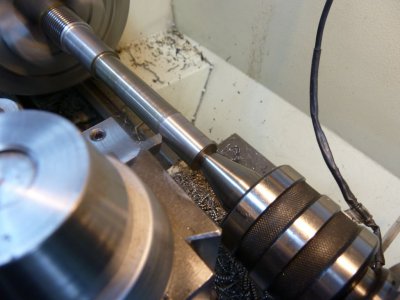
Photo #8 – Turning the new screw to size and using a vertical shear tool bit improve the finish.
Making the nut housing.
Next we make the housing that the nut will fit into. In most applications some type of a housing will be needed to support and locate the nut. This means that the outside dimensions of the new nut assembly will be larger than the one it is replacing and this may be a constraining issue that needs some study to find a suitable solution. In my case height was the key factor, the distance between the bottom of the mill table and the top of the original nut was about 0.250”, I felt I could use maybe 0.125” of that space but no more.
[FONT=&]
[/FONT]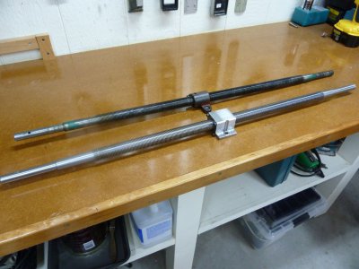
Photo #9 – The new lead screw and the original with nut.
That produced a housing of the dimensions shown in diagrams #1 and #2. Starting with a block 2 x 2 x 3.0” of 12L14 steel I milled the exterior surfaces to the needed size then chucked it up in the lathe to finish boring the hole that the nut will fit into. Since the nut has already been turned to its final diameter I finish bored the case so that it was 0.005” smaller than the external diameter of the nut.
Upon disassembling your lead screw and nut the first task is to measure the screw height and what other measurements that you may need to fabricate the nut. When you determine the dimensions for the nut case factor in an extra 0.025-0.035” in the base thickness. In a later step this will be milled off to insure the base is parallel with the axis of the screw.
When drilling the mounting holes make them over size to allow for movement during the alignment steps.
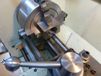
[FONT=&]Photo #10 – Finish machining the bore for the new nut.
[/FONT]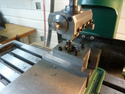 [FONT=&]
[/FONT] Photo #11 – Machining the cover plate from 0.125” plate.
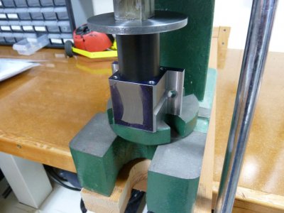
Photo #12 – Press fitting the new nut into the housing.
After trimming the new nut to length so that it stands proud 0.005” it is time to perform the final thread chase. I used the Dremel tool to cut six slots on the end of the new screw, the slots spanned four threads and were deep enough to cut into the base of the screw. I cut the chase at one end of the screw that will never reach the nut when installed and used in normal operation. If you have a small piece of material left after cutting the new screw to length then you may want to use that to make a chase from. Now that we have compressed the new nut into a housing that is slightly smaller than the nut we need to do another threading chase. To help the process along I place the new nut and housing in the freezer for an hour and then performed the thread chase as before.
Once the nut has been chased and you are satisfied with the operation of the nut on the shaft the nut needs to be trimmed to length. I re-mounted the assembly in the four-jaw chuck and faced off the excess acetal leaving it proud by 0.005”. I made the cover from 0.125” steel plate, after milling the plate to size I drilled and tapped for 10 x 24 socket head screw. Tightening down the plate will add further pressure to the nut so run the chase through once more to make sure there is no major change in the fit.
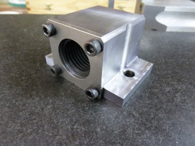
Photo #13 – The finished nut and cover.
Final measurements and adjustments prior to installation.
The nut and screw in my mill had a very large amount of slop. Had it not been for these excessive tolerances it would have been hard to crank the table because the combination of the base, the nut and the screw sat askew. It was the slop that allowed the screw to move to the proper position. It is important that when the new assembly is installed the bearing caps that the shaft rides in slip on and seat (mine have dowel pins to locate them) without any lateral pressure. I encountered several problems in this regard that needed to be corrected starting with a slight bow in the new screw shaft.
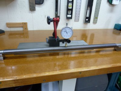
Photo #14 – Measuring the bow in the new screw.
The center point on the screw showed a total runout of 0.015”, by applying pressure with a “C” clamp and suspending the shaft between two “V” block I was able to reduce it to just under 0.003”. With the shaft and the new nut threaded half way onto the screw place the assembly on a surface plate measure the screw height for tilt. Both ends should be the same height if not then place the shaft on the mill as shown in photo #15 and take a light cut.
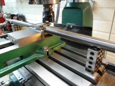
Photo #15 - Supporting the screw between two 1-2-3 blocks to remove any misalignment of the base relative to the shaft axis by milling a small surface cut off of the base block.
You should now have a shaft that is parallel to nut base. Next measure the shaft height and remove the amount of excess material needed to bring the screw to the proper height.
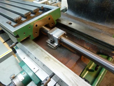
Photo #16 – New lead screw and nut ready for installation.
Despite my best efforts to obtain good measurements I managed to overlook a conflict between the corner of the nut housing and table end. If you look closely at the upper right corner of the table opening you can see where I had to grind out a small notch to allow the table to clear the nut housing.
The screw should be at the correct height but will probably need to be moved side-to-side in order to get the end caps to align with the table. I found this to be a trial and error process that requires some patience. While everything was apart I cleaned and lubed the ways and gib strip. Apply some way oil to the new lead screw, it will help smooth out the operation of the new screw and nut.
The original method used to retain the bearing assembly was to place the bearings and end piece in place then drill a hole through the end piece and shaft then fit a roll pin to hold everything. With a little use the bearings loosen up and add to the backlash. While machining the new screw I drill and tapped the bearing end to accept a ¼ x 20 threaded shaft. I made a brass washer with a recess to fit over the shaft and apply pressure to the hand wheel. The assembly is held in place with a nylon lock nut which provides the means to adjust the preload.
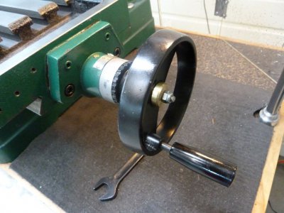
Photo #17 – Recessed brass washer and threaded rod used to apply preload to bearings.
After completing the assembly and adjustments I ended up with less 0.001” backlash, over time this will increase only slightly. On my lathe I used acetal to replace the cross slide nut more than a year ago and the back lash has now increased a little over 0.001”. Acetal is tough stuff and is a great replacement material for a lead screw nut, it will last far longer than its cast iron or bronze counter parts.
As always if you have any comments or questions please do not hesitate to contact me.
Jim


The following article describes the steps that I took to repair this specific mill but since much of this equipment is very similar others may find my experience with this project beneficial.
Where to start?
In order to have a smooth and uniform running lead screw, alignment is everything so the first step after removing the table is to measure things. Specifically the height of the screw above the base, diameter of the existing screw, position of the end cap shaft holes relative to the center of the existing nut, etc. A more subjective set of dimensions have to do with how much room is available for the new nut. I plan to use acetal plastic for the nut (more on that in a minute) which will require a metal housing to support and locate the new nut. The size of the housing will be somewhat larger than the original nut so an accurate estimate of the size is important.
From these dimensions I derived the location of the new screw center, the diameter of the nut, screw diameter, and the size of the housing that will hold the nut. Once I had this information I was ready to start fabrication. Diagrams 1 through 4 show the dimensions I ended up with.

Diagram #1 - Acetal nut housing.

Diagram #2 - Bottom view of nut housing.

Diagram #3 - Right end of lead screw.

Diagram #4 - Left end of lead screw.
Why acetal plastic?
The replacement nut for this project is made from acetal plastic (Delrin). I have used this approach previously with excellent results. I documented a previous project on using acetal to fabricate the lead screw nut for the G0602 lathe cross slide. You can find that article here:
http://www.projectsinmetal.com/foru...-cross-slide-more-accurate-and-less-backlash/
The original source material that got me interested in using acetal was a post by Evan Williams on the HomeshopMachinist web site. You may find that article here:
http://bbs.homeshopmachinist.net/threads/43645-Making-Acetal-leadscrew-nuts-the-easy-way
For the hobbyist using acetal in this application is in my opinion, the best and most viable of the options. Most hobbyists would have difficulty in doing the internal threading of cast iron or bronze which are the most common materials used. Heat forming acetal provides a near perfect set of threads. In most applications an external housing is needed to contain the nut and hold it in position. The housing must be small enough to fit within the space provided in your equipment but this is usually not a problem. Once the dimensions of the housing is determined and the housing is machined then the external portion of the nut is machined to fit the housing. A threading chase is made and the nut is run on and off the chase to loosen the threads. Overall, not a complicated process and the results are excellent.
Replacing the G3368 lead screw and nut.

Photo #1 – The new lead screw on the mill table that will use it. The new screw 1 x 36 “ at 10 tpi. No, I do not mill with a drill chuck, I was counter boring a screw hole.
After examining the lead screw and nut on my mill it became apparent that due to the wear on the screw that I would be better off starting with a new screw. I ordered a three foot piece of 10 tpi x 1.000” acme threaded rod. The original screw was an odd diameter, 0.949” or 26.7mm with threads at 10 tpi.
The first step was to prepare the acetal blank that will become the new nut. I used a piece of 1.625” acetal rod that I purchased from Enco. The rod comes in a white (natural color) or black, I used the black. I started by cutting off a 2.000” piece in the bandsaw. Acetal is very easy to machine, I left the outside diameter at 1.625” and using the lathe drilled a 0.875” hole through the center. I finished the hole to size with a boring bar. The hole size for making a nut is the diameter of the screw less one thread depth. In this case the screw was 1.000” and a 10 tpi acme thread has a depth of 0.050” so a hole size of 0.950” was needed. Once this was achieved the blank was split by sawing using a slitting saw on the mill.

Photo #2 – Sawing the nut in half, don’t worry if both sides are not exactly half heat forming will take care of the differences.
The next step before heat forming is to mill or cut the threads of the rod to make a chase. The threading chase will be used to loosen up the heat formed threads which after forming will have zero clearance and be very hard to turn on the shaft. Since this is a right hand thread we want the cutting edge (the edge perpendicular to the axis) to present itself when threading the rod into the nut. I used the mill to cut three slots that will act as chases. You may also use a Dremel tool with a cutoff wheel. In a later step we will use this method for the final chase. I preferred the mill technique since the slot is wider and will hold a larger amount of removed material without binding. If you choose to use the Dremel tool cut five or six slots along the axis that are deep enough to pass through the threads and into the screw base. This part of the new screw will eventually be turned down and this chase will not be part of the final assembly.

Photo #3 – The milled threading chase.
I used a bench vise to apply the pressure to form the nut, to support the nut halves I bored a hole in a piece of 4 x 4 wood and then trimmed it up in the table saw. This helps make the pressure uniform and also keeps the bench vise from becoming a large heat sink.

[FONT=&]Photo #4 – Blank halves in the wooden supports.
[/FONT] Since this is a relatively heavy piece of steel it needed some support else when the acetal reaches the flowing temperature the weight of the new screw will distort the nut.

Photo #5 – Lead screw with the blank halves clamped in the vise and a wooden frame to support the shaft during forming.
Heat forming is a slow process, the idea is to slowly raise the temperature of the rod which in turn will transfer the heat to the nut halves. Acetal will begin heat form at about 250 degrees F and will melt at 338 degrees F. I used a small propane torch to heat the screw, slowly heating both sides of the nut evenly, never allow the heat source to be pointed directly on the acetal material. This should take about 10-15 minutes, if you go too fast and end up with the screw too hot this will result in melting the material, go slow. As the nut begins to form continue tightening the vise until the halves come together. Excess material will form at the ends of the nut, when this begins you are done. Let the screw cool until you can handle it without gloves. Since the screw and nut have zero clearance you will need some mechanical assistance to remove the nut from the screw.

Photo #6 – Removing the nut, the pipe wrench will leave some marks but those will be machined off.
Once the nut is removed mount the screw in the lathe with the chase end exposed. I used a short piece of tubing to act as a spacer as shown in the next photo. I machined off the excess material and then began working the nut on and off the chase cleaning the chase after each cycle. This will take awhile, the acetal if pretty tough and although it machines very easily removing excess material with a chase is a slow process. On your first pass or two you will only go past two or three threads and then have to back off the nut and clean the chase. Each pass will go a little further than the previous.

Photo #7 – Chasing the thread, you may need some mechanical tools to hold the nut for the first few passes.
After you have finished the chasing the nut should move smoothly but not without friction, at this point in the process all we need is to have a nut that we can thread smoothly onto and off of the screw. Next finish machining the nut to size. In my case I had already determined the maximum size of the housing that fit into the space under the mill table. Working backwards I determined that a minimum case thickness of 0.060” was needed which meant the diameter of the new nut should be about 1.400” and an initial length of 1.750”. The new nut will be trimmed to the exact length needed after it is pressed into the case.
Machining the new lead screw.
Using the dimensions from the original lead screw I turned down the ends of the new screw. I am not sure of the material type the new screw was made from, it felt like 4140 MS. The turned finish was a little ragged and in the next photo you can see the results of using a vertical shear bit in the lathe to achieve a nicer finish. This tool does a excellent job on steel and only removes a few thousands at a time. I first learned of this tool from John Moran (aka Gadgetbuilder.com), you can see his write up here:
http://gadgetbuilder.com/VerticalShearBit.html

Photo #8 – Turning the new screw to size and using a vertical shear tool bit improve the finish.
Making the nut housing.
Next we make the housing that the nut will fit into. In most applications some type of a housing will be needed to support and locate the nut. This means that the outside dimensions of the new nut assembly will be larger than the one it is replacing and this may be a constraining issue that needs some study to find a suitable solution. In my case height was the key factor, the distance between the bottom of the mill table and the top of the original nut was about 0.250”, I felt I could use maybe 0.125” of that space but no more.
[FONT=&]
[/FONT]

Photo #9 – The new lead screw and the original with nut.
That produced a housing of the dimensions shown in diagrams #1 and #2. Starting with a block 2 x 2 x 3.0” of 12L14 steel I milled the exterior surfaces to the needed size then chucked it up in the lathe to finish boring the hole that the nut will fit into. Since the nut has already been turned to its final diameter I finish bored the case so that it was 0.005” smaller than the external diameter of the nut.
Upon disassembling your lead screw and nut the first task is to measure the screw height and what other measurements that you may need to fabricate the nut. When you determine the dimensions for the nut case factor in an extra 0.025-0.035” in the base thickness. In a later step this will be milled off to insure the base is parallel with the axis of the screw.
When drilling the mounting holes make them over size to allow for movement during the alignment steps.

[FONT=&]Photo #10 – Finish machining the bore for the new nut.
[/FONT]
 [FONT=&]
[/FONT] Photo #11 – Machining the cover plate from 0.125” plate.

Photo #12 – Press fitting the new nut into the housing.
After trimming the new nut to length so that it stands proud 0.005” it is time to perform the final thread chase. I used the Dremel tool to cut six slots on the end of the new screw, the slots spanned four threads and were deep enough to cut into the base of the screw. I cut the chase at one end of the screw that will never reach the nut when installed and used in normal operation. If you have a small piece of material left after cutting the new screw to length then you may want to use that to make a chase from. Now that we have compressed the new nut into a housing that is slightly smaller than the nut we need to do another threading chase. To help the process along I place the new nut and housing in the freezer for an hour and then performed the thread chase as before.
Once the nut has been chased and you are satisfied with the operation of the nut on the shaft the nut needs to be trimmed to length. I re-mounted the assembly in the four-jaw chuck and faced off the excess acetal leaving it proud by 0.005”. I made the cover from 0.125” steel plate, after milling the plate to size I drilled and tapped for 10 x 24 socket head screw. Tightening down the plate will add further pressure to the nut so run the chase through once more to make sure there is no major change in the fit.

Photo #13 – The finished nut and cover.
Final measurements and adjustments prior to installation.
The nut and screw in my mill had a very large amount of slop. Had it not been for these excessive tolerances it would have been hard to crank the table because the combination of the base, the nut and the screw sat askew. It was the slop that allowed the screw to move to the proper position. It is important that when the new assembly is installed the bearing caps that the shaft rides in slip on and seat (mine have dowel pins to locate them) without any lateral pressure. I encountered several problems in this regard that needed to be corrected starting with a slight bow in the new screw shaft.

Photo #14 – Measuring the bow in the new screw.
The center point on the screw showed a total runout of 0.015”, by applying pressure with a “C” clamp and suspending the shaft between two “V” block I was able to reduce it to just under 0.003”. With the shaft and the new nut threaded half way onto the screw place the assembly on a surface plate measure the screw height for tilt. Both ends should be the same height if not then place the shaft on the mill as shown in photo #15 and take a light cut.

Photo #15 - Supporting the screw between two 1-2-3 blocks to remove any misalignment of the base relative to the shaft axis by milling a small surface cut off of the base block.
You should now have a shaft that is parallel to nut base. Next measure the shaft height and remove the amount of excess material needed to bring the screw to the proper height.

Photo #16 – New lead screw and nut ready for installation.
Despite my best efforts to obtain good measurements I managed to overlook a conflict between the corner of the nut housing and table end. If you look closely at the upper right corner of the table opening you can see where I had to grind out a small notch to allow the table to clear the nut housing.
The screw should be at the correct height but will probably need to be moved side-to-side in order to get the end caps to align with the table. I found this to be a trial and error process that requires some patience. While everything was apart I cleaned and lubed the ways and gib strip. Apply some way oil to the new lead screw, it will help smooth out the operation of the new screw and nut.
The original method used to retain the bearing assembly was to place the bearings and end piece in place then drill a hole through the end piece and shaft then fit a roll pin to hold everything. With a little use the bearings loosen up and add to the backlash. While machining the new screw I drill and tapped the bearing end to accept a ¼ x 20 threaded shaft. I made a brass washer with a recess to fit over the shaft and apply pressure to the hand wheel. The assembly is held in place with a nylon lock nut which provides the means to adjust the preload.

Photo #17 – Recessed brass washer and threaded rod used to apply preload to bearings.
After completing the assembly and adjustments I ended up with less 0.001” backlash, over time this will increase only slightly. On my lathe I used acetal to replace the cross slide nut more than a year ago and the back lash has now increased a little over 0.001”. Acetal is tough stuff and is a great replacement material for a lead screw nut, it will last far longer than its cast iron or bronze counter parts.
As always if you have any comments or questions please do not hesitate to contact me.
Jim


