As part of the trade, I got a taper attachment for the South Bend Heavy 10. One of the problems with this one was that the cross feed screw assembly was broken.
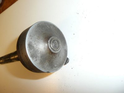
In order to fix it I needed some dimensions. I decided to take the ball crank of the Heavy 10 to measure what was there. In so doing I messed up the 12-24 threaded stub that secures the crank so now I had two screws to fix.
Taking the taper attachment screw apart I was left with this.

That’s a 3/8 shaft with a pinion gear on one end. The other end should have a 5/16 section with a key slot and a 12-24 threaded section. Not shown, the 3/8 broken end has a hole for a taper pin drilled about 3/8 back from the end. This retains a sleeve that bears against one of the thrust bearings that remove axial play.
I decided I would drill the broken shaft out to ¼” and then make an extension that would start with a ¼” shaft, and replace the 5/16 and 12-24 threaded section. This would be Locktited into the 3/8 shaft and the taper pin would go through it and fully anchor it in place.
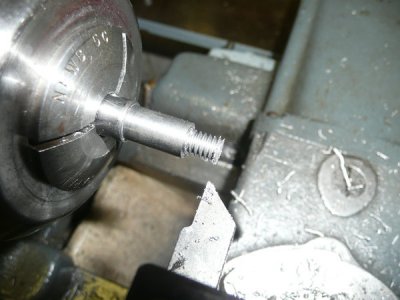
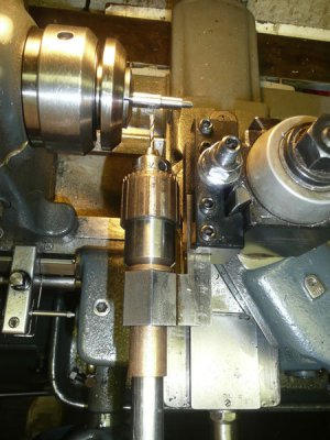
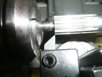
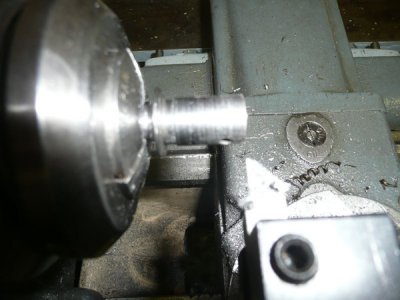
I started with a piece of 1144 3/8 rod and turned a 5/16 and a 0.215 section for the thread, and threaded the end stub. I only used the tool shown to be sure there was no radius in the steps.
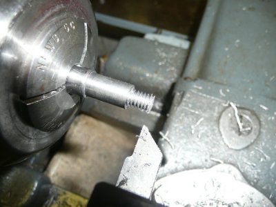
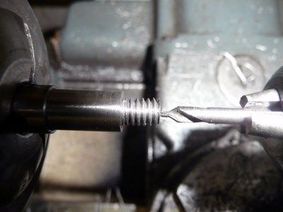
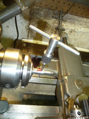
To assist in a future removal the threaded section was center drilled.
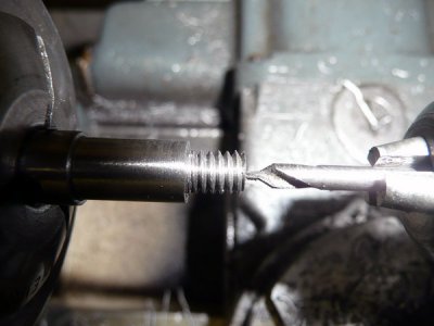
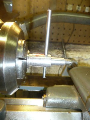
The part was then held in a 5/16 collet and a ¼” stub was turned.
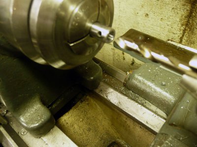
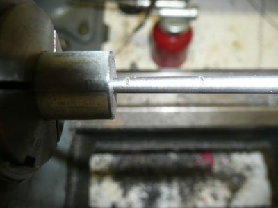
Next I held the remainder of the original screw on a 3/8 collet and faced, center drilled and drilled it out to ¼”.
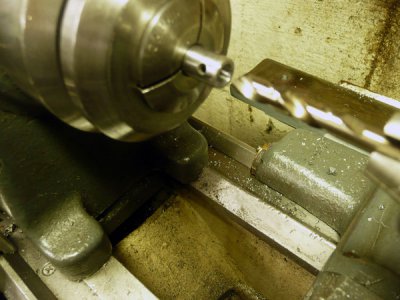
As I normally do I started with a smaller drill, 1/8 and went up in several steps so that the last cut was 1/64 or less. I find this gives a more accurately sized hole.
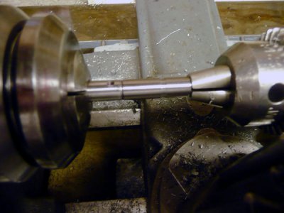
I cleaned the new extension and the hole with solvent and coated both with Locktite and using the lathe as an alignment jig let them cure overnight.
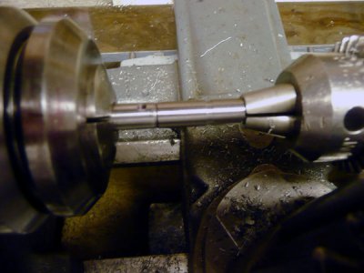
The ball crank is held in place by a round key, half fits into the 5/16 portion of the screw shaft. Half fits into the crank. You can put this in one of two ways. You can make a drill guide that slips over the 5/16 shaft but If your crank handle already has a grove you will need to make an entire new hole. Another way is to use a ball end mill and cut a half round grove. I chose to do the latter. Most of the keys I have run into are 3/32 in diameter but occasionally there is one that is 1/8” The key on my standard Heavy 10 screw was 1/8”
I mounted the screw assembly in a small index head using a 3/8 collet and supporting the screw end with a footstock center.
http://i50.photobucket.com/albums/f...chment/Cross Feed Screw Repair/slot-setup.jpg
The grove is cut 1/16 deep. I test for correct depth by laying a 1/8 rod in the grove and measuring over it.
http://i50.photobucket.com/albums/f...t/Cross Feed Screw Repair/measuring-depth.jpg
Next I needed to pick up the hole for the taper pin. Quite often SB drilled these by hand. There is no guarantee that they are on center or at right angles to the shaft. The hole diameter is in the 1/8” range, but it is tapered. I chucked a 1/8 pin in my cross drilling attachment, using that I found the center of the hole and setback of the hole. I determined that hole was on center and at right angles. It’s the first one I have found to be this way. Had it not been OC and true, I would have adjusted the cross drilling attachment to align with the hole. Once aligned I drilled out the hole to 0.120.
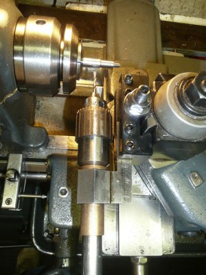
I then reamed out the hole with a taper pin reamer until I got a good fit with the bearing sleeve in place. (The red on the sleeve is there to mark the large end of the hole, there is only about 0.001” difference between the ends.
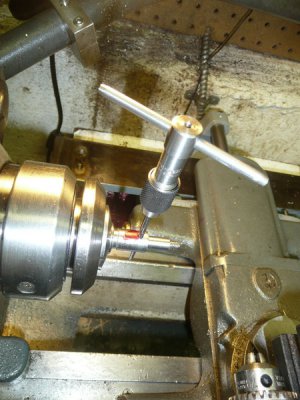
Reaming also meant that the old taper pin would no longer fit so I needed to fit a new one. I inserted a new pin and gave it a light tap home.
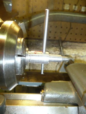
I marked the top and bottom of the pin with a coping saw.
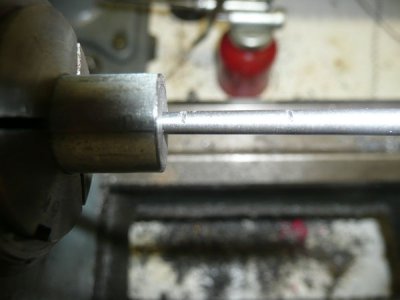
You can see the two scribe marks. The pin is being held in a tapered hole reamed to fit the pin. The pin is quite soft. I cut it off with the saw and then turned the fixture with the hole around where the hole diameter is a bit larger allowing me to cut the larger end.
With the new pin cut and fitted the repair I thought the screw was finished. No chance. When I assembled it I found there was quite a bit of axial play. The sleeve I had so carefully saved did not really fit. I needed to make a new one. But I did not like the condition of the thrust bearings so before I made a new one I decided to replace the bearings. I did not initially want to do this because it could mean making a new sleeve but now since I needed a new sleeve anyway I might just as well fit it to new bearings.
The original SB bearings are available from Grizzly, but at a price. MSC (and others) carry a similar bearing made by Boston Gear. Item #03548591 priced at $10.91. The price of these bearings has doubled recently. This bearing has the same 3/8 ID and 11/16 OD as the South Bend bearing but it MEASURES 0.027” thicker. In order to fit the bearings I needed to remove some material somewhere.
There was 0.012” of axial play and the bearings were 0.054” thicker that the South Bend bearings. I needed to remove. Around 0.042” . I decided to take part of it off the end of the pinion and part off the sleeve.
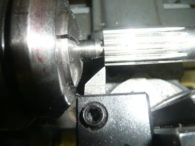
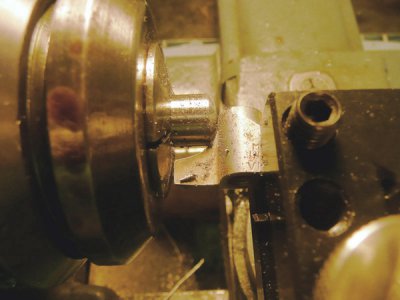
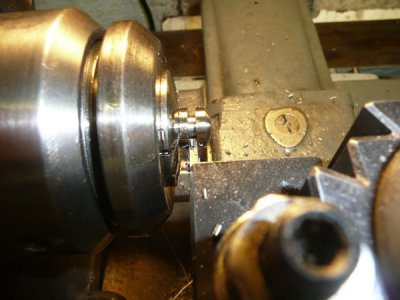
I used a similar pointed tool to remove the radius.
After cleaning the pinion up of any burs I assembled the parts again and measured the offset of the taper pin holes with drills. I took the rest off the sleeve, less 0.001 to 0.002 which I used for bearing preload.
To machine the sleeve I cleaned it up and super glued it to a 5/16 blank. I held this in a collet. The picture shows me facing the opposite end, which I also shortened. I forgot to take a picture of of the flange end.
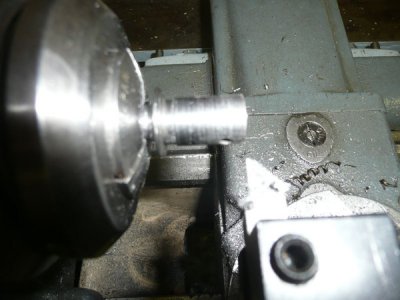
With the bearings fitted I needed to assemble the ball hand lever. The one that came with the attachment did not have a slotted nut. so I needed to make one of the curved nuts South Bend uses to secure the cross slide Ball Crank handle to the cross slide screw. Steve Wells does sell these for $9 each. I am refurbishing and installing a taper attachment on my Heavy 10 and the crank did not come with one. These nuts have a 12-24 internal thread, a ½” OD and one curved surface which matches the curve on the ball. The ball measures ¾” in diameter.
I started with a piece of ½” 1144 steel. I center drilled and drilled through with a #16 tap drill and taped through with a 12-34 tap.
Next I needed to round over the end. I used a HSS router 3/8 radius round-over bit. I held the bit by one end and brought in into the work forming the needed curve.
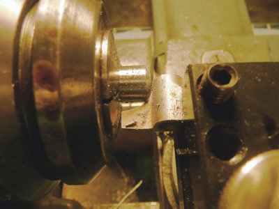
I then parted off the nut leaving it a bit oversize.
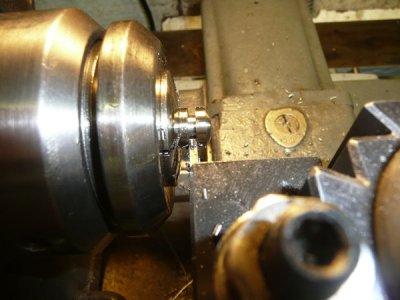
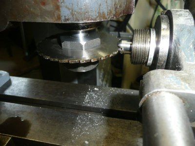
And I finally mounted it in the mill and cut the slot. Its 0.069” wide. (That’s the closest saw I have to 1/16”.)
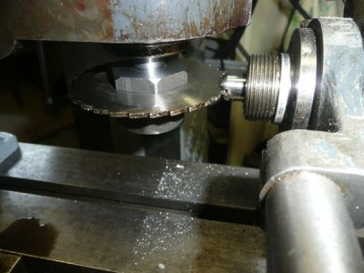
I assembled the parts, took a measurement of the nut and thinned it down to fit.
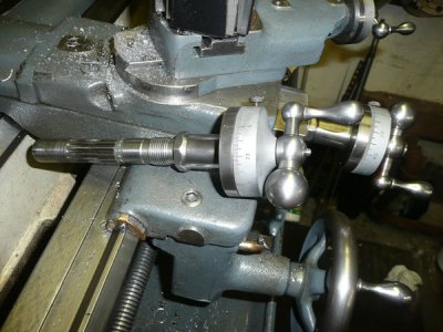
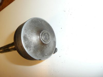
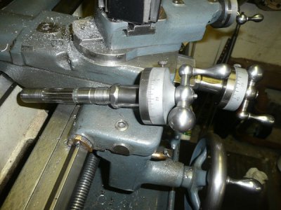
Here, finally is repaired drive.


In order to fix it I needed some dimensions. I decided to take the ball crank of the Heavy 10 to measure what was there. In so doing I messed up the 12-24 threaded stub that secures the crank so now I had two screws to fix.
Taking the taper attachment screw apart I was left with this.

That’s a 3/8 shaft with a pinion gear on one end. The other end should have a 5/16 section with a key slot and a 12-24 threaded section. Not shown, the 3/8 broken end has a hole for a taper pin drilled about 3/8 back from the end. This retains a sleeve that bears against one of the thrust bearings that remove axial play.
I decided I would drill the broken shaft out to ¼” and then make an extension that would start with a ¼” shaft, and replace the 5/16 and 12-24 threaded section. This would be Locktited into the 3/8 shaft and the taper pin would go through it and fully anchor it in place.
I started with a piece of 1144 3/8 rod and turned a 5/16 and a 0.215 section for the thread, and threaded the end stub. I only used the tool shown to be sure there was no radius in the steps.

To assist in a future removal the threaded section was center drilled.

The part was then held in a 5/16 collet and a ¼” stub was turned.
Next I held the remainder of the original screw on a 3/8 collet and faced, center drilled and drilled it out to ¼”.

As I normally do I started with a smaller drill, 1/8 and went up in several steps so that the last cut was 1/64 or less. I find this gives a more accurately sized hole.
I cleaned the new extension and the hole with solvent and coated both with Locktite and using the lathe as an alignment jig let them cure overnight.

The ball crank is held in place by a round key, half fits into the 5/16 portion of the screw shaft. Half fits into the crank. You can put this in one of two ways. You can make a drill guide that slips over the 5/16 shaft but If your crank handle already has a grove you will need to make an entire new hole. Another way is to use a ball end mill and cut a half round grove. I chose to do the latter. Most of the keys I have run into are 3/32 in diameter but occasionally there is one that is 1/8” The key on my standard Heavy 10 screw was 1/8”
I mounted the screw assembly in a small index head using a 3/8 collet and supporting the screw end with a footstock center.
http://i50.photobucket.com/albums/f...chment/Cross Feed Screw Repair/slot-setup.jpg
The grove is cut 1/16 deep. I test for correct depth by laying a 1/8 rod in the grove and measuring over it.
http://i50.photobucket.com/albums/f...t/Cross Feed Screw Repair/measuring-depth.jpg
Next I needed to pick up the hole for the taper pin. Quite often SB drilled these by hand. There is no guarantee that they are on center or at right angles to the shaft. The hole diameter is in the 1/8” range, but it is tapered. I chucked a 1/8 pin in my cross drilling attachment, using that I found the center of the hole and setback of the hole. I determined that hole was on center and at right angles. It’s the first one I have found to be this way. Had it not been OC and true, I would have adjusted the cross drilling attachment to align with the hole. Once aligned I drilled out the hole to 0.120.

I then reamed out the hole with a taper pin reamer until I got a good fit with the bearing sleeve in place. (The red on the sleeve is there to mark the large end of the hole, there is only about 0.001” difference between the ends.

Reaming also meant that the old taper pin would no longer fit so I needed to fit a new one. I inserted a new pin and gave it a light tap home.

I marked the top and bottom of the pin with a coping saw.

You can see the two scribe marks. The pin is being held in a tapered hole reamed to fit the pin. The pin is quite soft. I cut it off with the saw and then turned the fixture with the hole around where the hole diameter is a bit larger allowing me to cut the larger end.
With the new pin cut and fitted the repair I thought the screw was finished. No chance. When I assembled it I found there was quite a bit of axial play. The sleeve I had so carefully saved did not really fit. I needed to make a new one. But I did not like the condition of the thrust bearings so before I made a new one I decided to replace the bearings. I did not initially want to do this because it could mean making a new sleeve but now since I needed a new sleeve anyway I might just as well fit it to new bearings.
The original SB bearings are available from Grizzly, but at a price. MSC (and others) carry a similar bearing made by Boston Gear. Item #03548591 priced at $10.91. The price of these bearings has doubled recently. This bearing has the same 3/8 ID and 11/16 OD as the South Bend bearing but it MEASURES 0.027” thicker. In order to fit the bearings I needed to remove some material somewhere.
There was 0.012” of axial play and the bearings were 0.054” thicker that the South Bend bearings. I needed to remove. Around 0.042” . I decided to take part of it off the end of the pinion and part off the sleeve.

I used a similar pointed tool to remove the radius.
After cleaning the pinion up of any burs I assembled the parts again and measured the offset of the taper pin holes with drills. I took the rest off the sleeve, less 0.001 to 0.002 which I used for bearing preload.
To machine the sleeve I cleaned it up and super glued it to a 5/16 blank. I held this in a collet. The picture shows me facing the opposite end, which I also shortened. I forgot to take a picture of of the flange end.

With the bearings fitted I needed to assemble the ball hand lever. The one that came with the attachment did not have a slotted nut. so I needed to make one of the curved nuts South Bend uses to secure the cross slide Ball Crank handle to the cross slide screw. Steve Wells does sell these for $9 each. I am refurbishing and installing a taper attachment on my Heavy 10 and the crank did not come with one. These nuts have a 12-24 internal thread, a ½” OD and one curved surface which matches the curve on the ball. The ball measures ¾” in diameter.
I started with a piece of ½” 1144 steel. I center drilled and drilled through with a #16 tap drill and taped through with a 12-34 tap.
Next I needed to round over the end. I used a HSS router 3/8 radius round-over bit. I held the bit by one end and brought in into the work forming the needed curve.

I then parted off the nut leaving it a bit oversize.

And I finally mounted it in the mill and cut the slot. Its 0.069” wide. (That’s the closest saw I have to 1/16”.)

I assembled the parts, took a measurement of the nut and thinned it down to fit.
Here, finally is repaired drive.


