thlewe72---The lead screw is easy to change. Just pull back the spiral cover at the left end of the shaft and punch out the brass shear pin, then close the half nut on the screw and use the carrage to supple the force needed to extract the screw from the coupling. Also you need to be sure you have about 4 feet of clearance on the right side of the lathe to allow the screw to come all the way our.
-
Welcome back Guest! Did you know you can mentor other members here at H-M? If not, please check out our Relaunch of Hobby Machinist Mentoring Program!
You are using an out of date browser. It may not display this or other websites correctly.
You should upgrade or use an alternative browser.
You should upgrade or use an alternative browser.
Recieved the PM1236 metric to imperial kit today
- Thread starter Morgan RedHawk
- Start date
vballard -- thanks for the advice. that does sound easy. I had started taking the apron apart, and that didn't seem right. now I just have to move the lathe as the right side of my machine is too close to the wall. of course. thanks again.
Update to my progress -- the lead screw swap went well. I had to drill a 5/32 hole in the end for the shear pin which holds it to the gear box. Note -- there are TWO pins on the "left" end of near the gearbox. remove the one farthest from the gearbox -- mine was brass. dont try to remove the closer pin -- it wont come out.
I had to remove the apron box in order to change the half-nut, but that is pretty easy, once I realized that there are two pins which drop down from the top saddle (between the bolts). it takes a bit of wiggling to get the apron off around the various gears. But going together was much easier than apart.
I ran into an issue with the gear set however. the documentation which RayC has posted shows the 127t gear inside of the 120t gear. and a spacer/bearing behind the 127t. makes sense so that you can put the top 24t gear inline with the 127t and the bottom 48t, or move the 48t to to outer 120t for staggered turning. that configuration also matches the new feed chart plate that came with the conversion.
However -- on my lathe, the middle gear set is reversed -- the 120t is inside near the spacer/bearing and the 127t is on the outside. that configuration matched my old chart for the metric setup.
So it appears that the 120/127 gears are backwards between metric and imperial. Am I missing something here? should there be a new 127/120 gear set with the conversion kit? or do I have to press that bearing out and reverse it? (I'm worried about damaging it in the process).
so I'm almost done -- but now I'm confused about the gear setup. any advice would be appreciated.
-Tom
- Joined
- Nov 27, 2012
- Messages
- 7,857
Yes that is correct, the 120/127 would be reversed on the metric/imperial versions. So yes, the 127 would be on the inside (closest to the headstock). I just took a peek at mine, I don't see any reason why it couldn't just be flipped by removing the nut & washer then slid off the shaft. How does yours look like? The bearing for that gear looks different on both sides or does it sit offset or something? I never took mine off but the bearing looks the same on both sides & it's centered on the gear set.
I also received my cardboard tube of imperial parts earlier this week. Luckily, the ends were still intact and it appears that nothing had fallen out. I started with the tail stock since I thought it would be the simplest of the conversions which it was with one exception. The brass nut for the lead screw has a flange on it that fits over the end of the tailstock quill. On the original, there are three SHCS (5mm, I think) that connect the nut to the quill. The new nut does not have holes for these screws. I have a mill so I thought it wouldn't be a problem to replicate the bolt circle on the new nut. After an hour of futzing around with it I finally came to the conclusion that the pattern on the old nut is not a bolt circle at all. I am not sure what the pattern is but it is not a bolt circle. It is also not symmetrical. My first thought was to put the two nuts flange to flange and use a transfer punch to mark the centers of the new holes. That wouldn't work though since the holes were not symmetrical and putting the parts face to face makes a mirror image not a true replica. After thinking about it for a while, I realized that there really isn't that much precision needed. There is a flat milled into the flange to allow the flange to clear the key/keyway that prevents the quill from turning in the tailstock. As long as that flat is roughly in the right place, the orientation of the flange is not really critical. I ended up taking careful measurements of the original using the DRO on the mill and located the holes on the new part that way. It was not difficult but it was time consuming. After the holes were drilled and the new nut installed in the quill I was able to put everything back together. My quill was very tight going back in and getting the key aligned with the keyway was a little tricky as a result. After a while I was able to get it to slide into place and the rest of the assembly was relatively uneventful. Hopefully, this will save some of you some time.
thlee72, I will be interested to see what you figure out with the gears since I am pretty sure I will have the same situation. Thanks for posting what you have done so far I am sure it will help me when I do the remainder of my conversion.
thlee72, I will be interested to see what you figure out with the gears since I am pretty sure I will have the same situation. Thanks for posting what you have done so far I am sure it will help me when I do the remainder of my conversion.
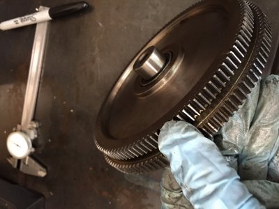
Success. I was able to remove the center bearings and spacer from the gear set and reinstall them the other way around. There are actually two bearings and a snap ring in between -- which is why I was unable to press them out as a unit. you have to press just spacer first. that will pop out the space and one bearing. Press from the side OPPOSITE the space (away from the center). then the second bearing came right out after removing the snap ring. This was not obvious from looking at it.
anyway -- its back together and working great.
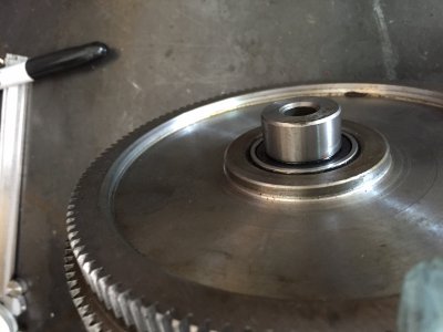
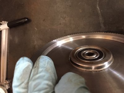
here are some pictures of my gear set and the spacer bearing.


anyway -- its back together and working great.
here are some pictures of my gear set and the spacer bearing.


- Joined
- Mar 22, 2013
- Messages
- 498
Hey guys, was just about to reply, but looks like you have it all figured out, you guys are amazing! No need to send any parts back, just keep them in case they ever would come in handy for you.
I am working on a set of instructions, but looks like everyone beat me to it!
And Val yes I got your email, I will take care of it. I do not know how they were missing, I packed that one up, personally, it was the first one. I set the dial on the desk beside it, but everything else was in there when sent, so no idea on that one. And for Richard, I have those ordered too, no big deal though on either, they will come by air, right after the chinese holiday coming on Oct 1st. They get more time off than we do, that is for sure!
Thanks thlee72! I am still not clear what needs to be done on the gears. Is the desired end result that the shaft protruding in the first two picture needs to be flush as shown in the third picture? If I understand you right you must press it out from the flush side and then reinstall it from the big gear side? Is that right? That seems to indicate that the shaft has a shoulder on it that prevents it from being pressed flush from the protruding side. Does any of this make sense?
Also, on the leadscrew, I assume you had to remove the spiral covers to get the apron off. When you disconnected then did they unwind like a spring? Once you had the shaft unpinned on the left, was it free to push out the right side or did you have to take the right side loose somehow? did you have to drain the oil from the apron to change the half nut or just move it back enough to get space to work?
Do you have any advice on getting the angles right on the compound leadscrew? I have mine adjusted pretty well but it could be better I think. It is smooth as butter going clockwise but a little tight in spots coming back the other way. It is not terrible, just not as smooth as the other way. I am not sure how an angle being off would cause different behavior in different directions. I was thinking maybe one of the pairs of thrust bearings was messed up somehow but they seem to be fine. The only way to adjust it seems to be to take it nearly apart, tweek the nut a little then reassemble and try again. Did you find a better way?
I found I had to temporarily loosen the back-splash and push it back out of the way in order to get the cross slide back far enough to get the nut out. There are two small grub screws on the nut that I assume are for taking out backlash. I just screwed them in until they touched the main part of the nut but didn't put any pressure on. Do you know the correct procedure? The cross slide is working great but I want to make sure I get the nut adjusted correctly.
Sorry for all the questions. Thanks for blazing the trail! Matt, obviously I am not as experienced as thlee72, I wouldn't mind seeing your instructions!!

