Radius to a flat on a Rotary table - Order of Operation?

Just for fun

Tim Young
H-M Lifetime Diamond Member
Joined
Oct 7, 2020
Messages
2,116
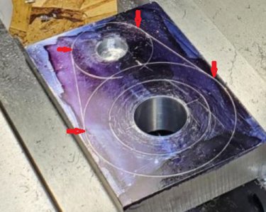
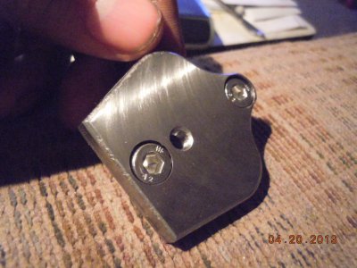
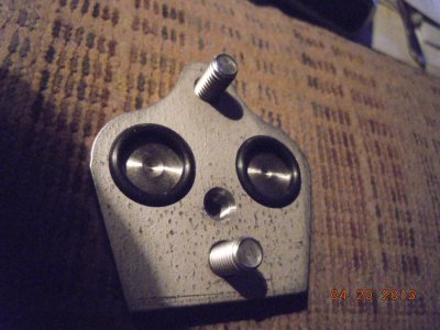
I am making a tailstock DRO setup for my lathe. This is the part for the ram, I painted it with dykem and lightly sketched it out. Which also left lines on my part that I would just as soon not have. My first order of operation was to bore the holes. Once I had that done, I trimmed it down on the band saw and then cut the flats, and this is where my question lies. Unfortunately, I did not take enough photos, but here is how I set it up (There has to be a better way). I lied two parallels on top of the vice and then lined up my line that I drew to the top of the parallels and cut the flats. On one side I did really well but the other I didn't cut it enough; I'm hoping you can see it in the fifth photo.

So, my question is how you would measure or set this item up to cut the flats as to have a nice tangent between the two radiuses and the flats.

Screenshot 2023-06-28 214339.png

20230625_161813.jpg

20230628_112836.jpg

20230628_162246.jpg

20230628_162304.jpg
 
You could ream two holes first and mill the flats using gauge blocks and dowels through the holes, like using a sine bar. Machine the flats to the dimension measured from the pins.
 
can you still set it up on either arc in the RT? set center to X0 Y0. move Y to surface of arc. Then just move your X axis to tangent point on arc2 and move RT in until it touches off
 
can you still set it up on either arc in the RT? set center to X0 Y0. move Y to surface of arc. Then just move your X axis to tangent point on arc2 and move RT in until it touches off
I'm pretty sure I can fix the mistake. But still unsure of the correct way of make this part to start with. Is there a better way then laying it out on the surface and milling to the lines? How do I determine the Tangent Point?
 
arrows
 

Attachments

  • Capture.JPG
    Capture.JPG
    70.5 KB · Views: 7
This is a part I made with lots of tangent edges. The entire part was done on the RT.
Lots of math but it looks like you cave CAD to do the heavy lifting.
Using the CAD you can easily lay out the angles where the tangent points are located.
I started with an outer large radius, this radius is tangent to an angled side and also tangent to the next inside R.
I set the center of the arc on the center of the RT
Then offset the "Y" axis to the R + 1/2 the cutter DIA.
set the RT to the 15° angle of the side.
Using the x axis I made a cut starting off of the part up the zero on the "X" axis.
stop there and rotate the RT to the angle of the tangent point.
The move the part to the next center point, set cutter offset, and start with the RT at the previous tangent point and rotate thru to the next tangent point. Repeat till done.
The part pictured was 5 setups, one for each radius.

The I went all around once more with a 1/16R corner rounding end mill. so it was 5 more setups. I had to make 20 of these out of 304 SS.

So the flats are cut on the RT which will guaranty tangent. Cutting the flats and then trying to match the radii to them is real hard.
 

Attachments

  • Anti Dive Blockoff MKII 001.jpg
    Anti Dive Blockoff MKII 001.jpg
    230.2 KB · Views: 9
  • Anti Dive Blockoff MKII 006.jpg
    Anti Dive Blockoff MKII 006.jpg
    229.8 KB · Views: 9
  1. Center your spindle axis on the RT axis and set your X and Y coordinates to 0,0 . Set your RT to 0º.
  2. Clamp your work piece to the RT so the 40mm hole will be centered on the RT axis.
  3. Bore the 40mm hole.
  4. Move the table to y = 44mm and bore the 12.7mm hole.
  5. Move the table to x = 30mm +1/2 the end mill diameter and y = 50mm
  6. lower the mill mill and cut a straight path to y = 0mm
  7. Cut the large arc by rotating the RT to 163º
  8. Without changing the RT angle, now cut the second straight to y = -50mm
What remains is to cut the second arc. Reposition the table to 0,0 and move the work so the 12. 7mm hole is at the RT center (a 1/2" dowel pin will facilitate the centering. The tricky part is to reorienting the work to the RT rotation, I personally wouldn't bother with hitting it exactly. With the work repositioned, I would offset my table to x = 17.4mm +1/2 the end mill diameter and y =0mm and cut the small arc by eye, rotating the RT. I would stop just short of hitting the tangents to the lines and blend in the final few thousandths.

II would also make an initial pass about .15mm oversized to allow for a finish pass.
 
I've modified my rotary table and toolmakers vice to align together as the video. With my setup I would use a machined block +0.002" on the width and length. The thickness would allow for clamping in the vice, leaving the part thickness above the jaws. The system allows for the vice and part to be moved easily to any known position from the centre hole using a dowel as a moveable stop. Machine off the back to thickness at the end.

See the video, it will probably make more sense than my description.
 
Thanks for the info guys.

@Flyinfool Very cool, Thank You. I fully understand about cutting the flats first being the hard way to do it. I might just have to make another one just to see if I can do it right,

@RJSakowski
I'm starting to get a little better understanding of the process; but I'm having a hard time following your math. I'm following along up to item #4, then you lose me on item 5. I get the basic idea now anyway.
It can be difficult to visualize. Myself, I had to actually go down to the mill and cut air. I chucked a pencil in the milled and traced out your part.
The basic idea is that you can efficiently cut arcs on a manual mill with an RT. The center of the arc is always at the RT center, the radius of the arc is determined by the distance of the mill spindle axis to the RT center, and the amount of rotation determines the length of the arc.

The distance between the spindle axis and the RT axis is the hypotenuse of the triangle formed by the x and y movement. It is simplest to only move either x or y.

Finally, straight cuts can be made at any angle simply be rotating the RT to the desired angle.

The math can get a bit hairy doing all this as well as keeping track of all the positions if you don't have a DRO but it is possible to cut complex profiles even so.
 
Back
Top