Quarantine Projects!

If only I was only 30, I remember back 46 years ago when I was. Just starting out in Marine engineering, good salary and rarely more than 60 hours work a week, regular long holidays. Life, as they say, was a beach. That was before the socialists came in and wrecked the place. We are still recovering. I admire your drive and skill. You have a good wide range of skills for only 30, and your command of English is also very good, I wouldn't be surprised if you spoke half a dozen other languages. Good luck keep up the great work.
 
Just finished a small modification to my belt sander.

This motor operates in close proximity to very abrasive grinding dust. I was starting to get nervous about the fan sucking in the dust and ruining the motor. So I figured I'd try to make a cover for the end.

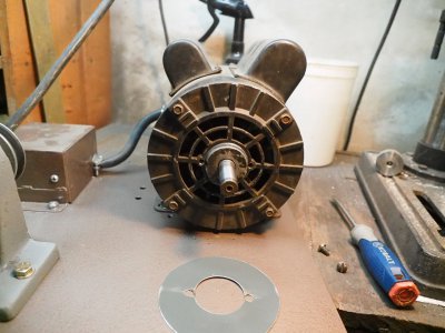
This is what the end looks like, open.

EM520875.JPG


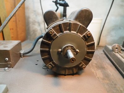
My cover is just a very thin aluminum sheet that blocks the fan end from sucking in dust.

EM520874.JPG


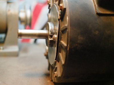
I peeled the rear facing edge away slightly to allow at least some air flow. This edge faces away from the belt.

EM520876.JPG


I'll keep an eye on motor temperature but usually it only runs for a few minutes at a time and then at pretty light loads. I think it'll be fine but if it starts to get hot too often I'll peel back some more of the cover.
 
I think you will find it's going to over heat if run for any meaningful length of time. You might try putting some kind of cloth or foam filter on the inlet side, and see how that works. Leave the outlet side open. Mike
 
Yea, that's a possibility I guess. Maybe I could drill a few big holes in my aluminum cover and sandwich a piece of clothe or coffee filter between the cover and the motor. That's a good idea, thanks @FOMOGO!
 
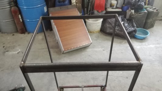
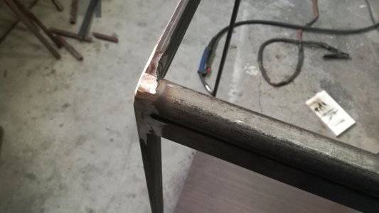
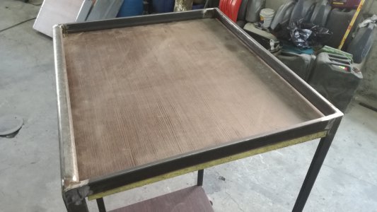
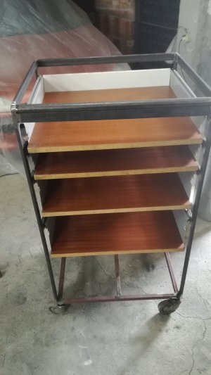
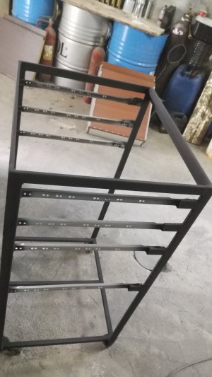
Part 2 on quarantine project No: 2 , i continued with the frame, cut the tubing and welded them, i used a round bar and some sheet steel on the front to make it more comfortable to work on it, i also rounded the edges and fully welded the open tubes and grounded them smooth, then come to find and fit the top and bottom i used some darker color with a bit of texture so it can take a beating and not look awful. Then came the difficult task of fixing the drows, i had to weld on extasons because the slides did not reach, i did fix them first by screws but then welded them. Last thing i did is to disassemble it and paint the frame. I used truck bed liner thinned so i can apply it with a paint gun, my thinking is should last longer. The plan going forward is to assemble it, cut and fix the draw faces and handles and wrap the entire cabinet in zinc plated sheet metal.
IMG_20200426_113215_1.jpgIMG_20200426_120739.jpgIMG_20200426_124151.jpgIMG_20200426_125414.jpgIMG_20200426_154656.jpgIMG_20200426_162427.jpg
 
That's shaping up pretty good @GoceKU. You're gonna gain a lot of storage space with that! Minimal footprint too.

I just finished another small upgrade on the lathe.

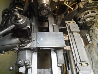
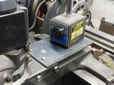
I made a more robust cross slide cover. With this I can mount a mag base indicator and finally measure tool height to get on center. Believe it or not I've never once measured my tool height!

The cover is 3/16" thick and about 3-1/4" wide by 5" long. I had to drill/tap two additional holes in the cross slide. The original screw is the one in the middle but it proved insufficient to anchor the plate in a satisfactory manner.

EM520878.JPG


Mag base! The cover doesn't move or flex at all. Very solid!

EM520879.JPG


I'm not sure what else I can do to this lathe. It's in a much better place than it was at the end of March, that's for sure! I should probably check the alignment...
 
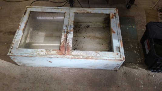
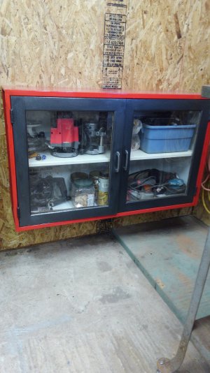
Now I have the space for them I decided to clean up these two cabinets and put them to good use. This one had a broken glass on one door. I removed the glass from both doors and replaced them both with plexiglass. Cabinets are 47" x 28". Here is one and the other will be installed on top.
KIMG0048.JPGKIMG0052.JPG
Thanks for looking.
Jay
 
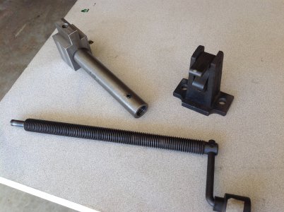
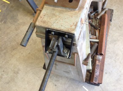
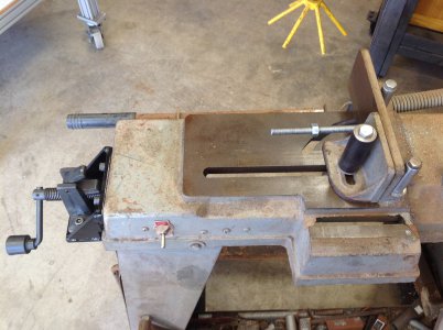
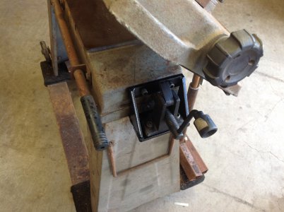
I got a chance yesterday to make the final push to adapt the speed vise I picked up in a yard sale years ago to my HF 5x6.
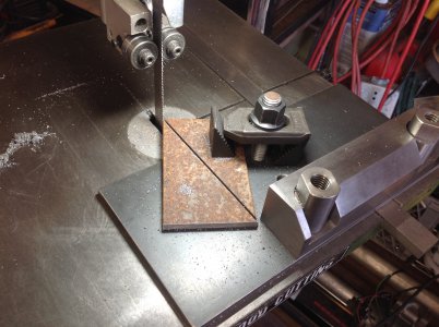
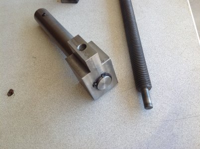
Besides machining the block and shaft I'd also decided to thread the inside of the adapter shaft to make a more positive link to the lead screw. It was 18mm X 2.5. It also has a set screw for little pilot that sticks out the end of the lead screw. Not perfect but another lessonlearned. The big challenge for me was to mount to the body of the saw because nothing is square because of draft when they cast the base. Rather than grind or machine the end of the base I went with adapting to the angle of the schwangle. It works so i guess it's ok. I'll probably have to do a project where I'm using the saw a lot to know for sure where I screwed up. One thing is the crank handle hits the saw arm if it's all the way down and the vise is all the way closed. But with my homebrew stop it never has to be all the way down now so not a problem, yet. I also included a pic of cutting the sides for the mount on my HF vertical bandsaw with the supergofaster highly modded auto sled.
 

Attachments

  • image.jpeg
    image.jpeg
    1.6 MB · Views: 28
  • image.jpeg
    image.jpeg
    2.2 MB · Views: 24
  • image.jpeg
    image.jpeg
    2 MB · Views: 25
  • image.jpeg
    image.jpeg
    1.5 MB · Views: 25
  • image.jpeg
    image.jpeg
    1.6 MB · Views: 25
  • image.jpeg
    image.jpeg
    1.3 MB · Views: 32
Last edited:
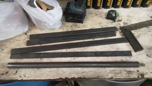
I finally got a metal project done, since COVID-19 is keeping the building inspectors away and has left my shop project at a standstill. This is a stand for my Lagun mill. It is 1x2 CRS that supports big 3/4 thread poly mounts. Should keep the mill level.
bc46873fd6238e3b192b6e5e5daa19b8.jpg
 
Back
Top