Purpose of pin on Atlas 10D headstock spindle shaft

frankonthetis

Registered
Registered
Joined
Dec 10, 2016
Messages
20
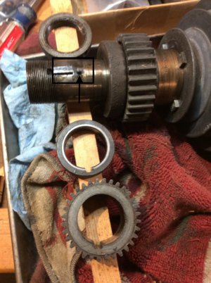
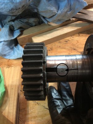
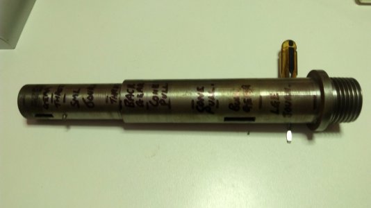
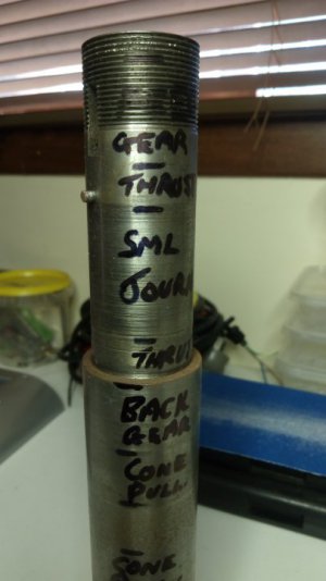
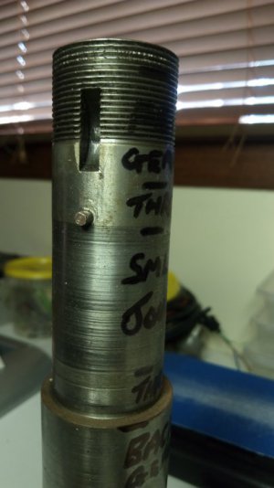
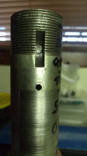
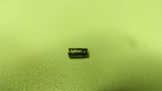
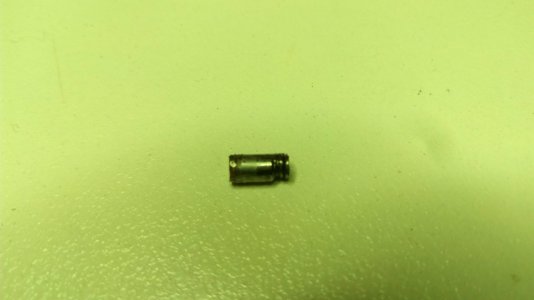
Did find a discussion here some time back about this pin on the headstock spindle. Failed to Bookmark so have to ask the question. Have taken apart a 10D to replace broken/brazed & missing parts. Found this pin and it would neither screw out or be pulled out after using fluids. Ended up breaking it and gently filed to the shaft. Question 1. is it needed? 2. purpose? 3. should the broken bit be drilled out and replaced?
Suggestions/comments appreciated. Thanks, Frank
 

Attachments

  • h:s spindle c:w pin.JPG
    h:s spindle c:w pin.JPG
    87.2 KB · Views: 52
  • filed smooth.JPG
    filed smooth.JPG
    66.3 KB · Views: 50
Frank,

1. Yes
3. Yes
2. The pin is Atlas part # 9-116. The name is "Spindle Thrust Collar Pin (Not Illustrated). Its purpose is to keep the inner race of the spindle thrust bearing from not rotating, but spinning on the spindle. It is only used on the babbit bearing spindles and is not shown on any of the unmodified factory parts drawings and not even called out on most. It is called out on the Craftsman 12" babbit bearing models but is not shown on any.

My suggestion before you attempt to drill out the remains and make one is that you call Clausing and see whether of not they still have any. Then speak with a tech support person (probably Tom McNett) and ask him to send you a scan of the 9-116 and the 10-31 Spindle. And if you will forward the files to me, I will clean them up and upload them to Downloads. I would prefer to have the original .TIF drawings as it would save me the time and trouble of converting the .PDF's to .TIF's. If you cannot view .TiF's ask him to send both. I happen to know that when all of the old Atlas drawings were scanned, they did it as .TIF's. The reason for asking for 10-31 is that the drawing will have the hole dimensions on it. Which you are going to need.

Am I correct in thinking that you had to cut off the exposed part of the pin before you could get some of the parts off of the spindle?
 
Thanks for your response Robert. Will contact Clausing and talk to Tom McNett about the 9-116 and 10-31. Yes, we actually shredded the pin using vice grips to try and remove it. Unsure what the metal was but it certainly was soft. Everything behind it in the picture did come off after the pin was filed level to the shaft.
Frank
 
OK. I thought that the pin had to come out before you could strip the spindle.
 
Robert

Spoke to Ron McNett at Clausing this morning and he sent me the two documents you mentioned. They are .pdf and hopefully they come through.

Frank
 

Attachments

  • 10-31 Head Spindle.pdf
    303.9 KB · Views: 15
  • 9-116 Spindle Thrust Wshr Pin.pdf
    32.5 KB · Views: 11
Robert, a clarification please on the 9-116 & 10-31 drawings. Need to understand how to interpret these schematics, is the 9-116 showing the hole as 1/8" wide by 1/4" deep? On the 10-31 drawing it shows #31 [.120] drill x 3/16 DP 2 holes. There was only 1 hole in my spindle shaft.
Your help and knowledge is much appreciated.

Frank
 
Original spindle from my 10f, pin needs to be removed if disassembling anything from the spindle to the right of the small journal.
The pin locates the outer plain thrust bearing so it rotates with the spindle.
Pin was rather difficult to remove.
At first glance, the pin appeared to be threaded, poorly.
No sign of any thread in the hole, so that's ruled out.
Difficulty level and post removal damage on both ends of the pin(I only wrecked one end) screamed "I've bin spot welded".
Possible but not factory, seeing as you can't remove the thrust ball bearing without removing the pin.
I went with new spindle(journals were good, looked a bit rough but measured up spot on.) and put another thrust ball bearing on the other side(outer) of the small journal. Didn't need the pin after that.
 

Attachments

  • IMG_20220127_095619.jpg
    IMG_20220127_095619.jpg
    79.1 KB · Views: 20
  • IMG_20220127_100049.jpg
    IMG_20220127_100049.jpg
    40.6 KB · Views: 12
  • IMG_20220127_100114.jpg
    IMG_20220127_100114.jpg
    42.4 KB · Views: 12
  • IMG_20220127_100251.jpg
    IMG_20220127_100251.jpg
    41.1 KB · Views: 12
  • IMG_20220127_101444.jpg
    IMG_20220127_101444.jpg
    70.2 KB · Views: 15
  • IMG_20220127_101515.jpg
    IMG_20220127_101515.jpg
    69.7 KB · Views: 25
We have the spindle drawing and the pin drawing. The spindle drawing actually shows two holes but can't determine what the left one is for. The two or three people who have disassembled a babbit spindle only found one hole in their spindle, the right hand one from the drawing. The pin drawing show it to be 1/8" dia. by 1/4" long. The holes are made with a #31 drill (0.120 In) x 3/26" deep. Which at least explains why they are so difficult to remove.
 
How far apart are the holes according to the drawing?
Perhaps original spec. was two holes/pins for the plain thrust bearing.
 
No, that I probably would have figured out. But they are both at the same relative o'clock position, or both drawn at TDC. The drawing shows the spindle with the coarse nose threads at the right end and the fine threads for the large nut on the left end. The hole for the thrust bearing pin is 1/8" to the left of the shoulder between the smaller diameter for the spindle gear and left bearing and the larger diameter for the pulley, bull gear and right bearing. The second hole is 1-7/8" toward the smaller end of the spindle. which would I think put it just outside of the left spindle bearing. Maybe they originally planned on another thrust bearing but decided that it wasn't needed. And forgot to remove it from the drawing. Maybe the 9" has both holes,
 
Back
Top