Problems with my digital dash from high energy interference

If there’s just one component affected I’d shield that rather than trying to chase down every other thing that could be causing the problem.

Honestly, if the support I got from that manufacturer was “must be something else, you fix it” I’d be inclined to put it back into the box and send it back for a refund.

They should know it’ll be in a noisy electrical environment and should have engineered the required shielding into their product IMHO.

John
Absolutely! I’m so tired of ”well you bought it, you fix it”. Lame stuff like that vague “shield it” is not customer care. Personally I think there’s something wrong with the dash unit.
 
Autos are a severe EMI environment- often with stereo systems power line filters are required to kill both ignition noise and alternator whine
One suppression method doesn't always fit all cars and configurations
Often a circuit will work fine on the bench and go absolutely nuts when installed in a car
 
I just asked some more questions of tech support because the first reply was it is "interference from an energy source" causing the problem and received this second response. I completely agree that they should know on a 1955 chevy it would most likely have a sbc in it and the oil pressure sender is right beside the distributor, and a very common swap is using a hei one wire ignition. But it is what it is and I have to deal with it. I'm not sending it back.

There is electrical interference, it is coming on the board from some wire running close to a high energy source. I would start with oil pressure sender wiring since it is usually close to the distributor. Disconnect the sender wires 1 by 1 at the dash and watch for the interference to go away. The ground and power wires can also be affected if your ground is close to the distributor it can be the cause . When the source of the interference is found, reroute the wiring and shielded with something like rubber hose or a commercial brand shielding. "

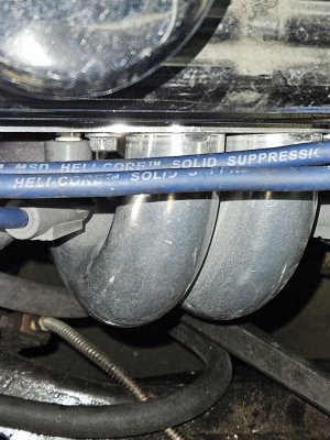
Pic of my plug wires. They were on with the old points style distributor and I changed the distributor terminal end to match with the hei cap. Was trying to save a few $$$. Not sure if they are up to being used with an hei setup. Supposedly standard external coil setups are 30k volts, hei is 65k. I guess I need to use the old trick of running the engine in the dark to see if any of the plug wires are arcing out.

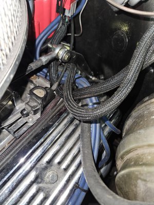
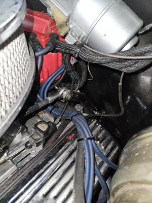
Second pic is how the wires to the distributor and pressure sending unit, both wires are actually contacting the plug wires. I moved the wires, had them under the throttle linkage so when it moved back there would be no interference with the arm. The clear now barely, but not by much. But they are still close to a couple of plug wires. If this fixes the problem then I'll do some more with the routing and some sheilding. Now that I know what the problem is I can try different things to fix it.

20230531_135935.jpg20230531_135757.jpg20230531_144504.jpg


"
 
I’m glad you got more info from them, yes they should be aware of the potential for your problem and be willing to assist.

I’m not sure I’d use rubber hose as electrical shielding though.

Good luck,

John
 
This is another been there, done that. The upside is you have a strong ingition system!

The speedo sensor sends pulses to the ECU or dash. Replace that run of wire with steel braided, twisted pair. The twisted pair will buck A/C noise, and the shield should be grounded by the drain wire to good GND at the ECU or terminus.

You should also do this with your TPS, CKP, CPS, crank trigger, and any other multiwire sensor. The wires are not power transmission leads, they are signal wires, and signal wire is another word for accidental antenna. Shielded cable is an easy fix, just don't ground both ends, or the ground loops will make other noise.
 
Yeah I don't think a rubber hose will do much at all. It may insulate it, but probably do nothing for interference.

Yes I have a great ignition system. It barely fits, but a miss is as good as a mile they say.

I have a twisted pair setup from AAW that I didn't use for the pulse generator. But I'm going to do one thing at a time. I don't want to to a shotgun approach and do multiple changes at once, if I did I'd never know what to focus on.
 
Another couple of ideas:

The shielded cable should help a great deal but also:
Get the signal wiring away from the ignition wiring as quickly as possible. Route it in the wrong direction if that gets more distance sooner.
If you have to cross over ignition wiring, do it at exactly 90 degrees (perpendicular) to the ignition wiring. Add a gap of an inch or more at
the cross-over if possible.
If you end up with a filter, a big capacitor like the 500 uF, shown above, can be aided by paralleling with a smaller one, such as a 0.1-0.22uF
For such a filter, the capacitor leads must be very short to be more effective, especially the 0.1uF - 0.22uF one.
 
Back in the seventies, I was dealing with electrical noise from my HEI system interfering with ham radio reception. I shielded the plug wires with copper braid.

A good source for braid would be RG58 coaxial cable. Strip the outer jacket to expose the braid. By pushing the braid, it will increase in diameter and it can be slid off the inner conductor,

Thread the braid over the plug wires and pull it to close neatly on the wire. I bonded the braid to ground at the distributor. I had also made a cover for the distributor to prevent noise from it.
 
That's a good tip about the RG58, that's easy to come by as junk. Wire braid of any form is dear in cost.

When I build my EFI systems, I divide the signal harnesses from the power harnesses, or better stated, the sensors from the actuators. On my Honda, I was able to keep the power all on one side of the engine bay and the signal on the other, meeting at the engine. It was a nerd thing to do, but externally driven LS1 truck coils are like a loaded gun that you don't want misfiring from noise on a wound out little Honda running well above 100% volumetric efficiency.

I set up thermocouples to let the ECU read and datalog each cylinder's EGT. I built the sensor driver circuits into the ECU, so the raw signal has to travel by wire all the way back to the interior firewall. Bear with me, I have a point. Thermocouples produce a very very tiny change in voltage in response to temperature. To a computer sampling at 250 Hz or more, the effect of noise floor is the bigger issue. Which is why type-k thermocouples in automotive racing and in industry are always shielded and always twisted pair. It's the most interference-sensitive sensor I can imagine to put in an underhood environment, but it works because of those tricks. Hall effect crank triggers are another sensitive one, not nearly as sensitive but hall pickups are shielded/twisted much of the time. OEMs cheaped out by shortening the wires and are mounting conditioning circuit modules right on the engine block in order run an insensitive amplified signal back to the ECU.
 
I was going to suggest the same on using RG58 or if one has short sections of braided fuel line that are not useable.
Pierre
 
Back
Top