Problem with the control for my power draw bar

ScrapMetal

Active User
Registered
Joined
Apr 6, 2011
Messages
2,082
I'm not quite sure what I should try next.

The "IN/OUT" box was having an issue when it was under pressure. The air was seeping out at a good rate from where the arrow is pointed. The draw bar would still function but was not real responsive.
(The rag is around the base to catch the excess oil included with the "air" but I don't run it that way.) :eek:
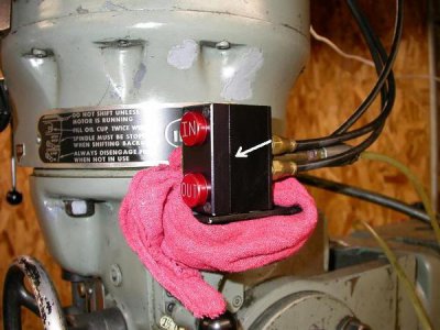
aircontrol01.JPG

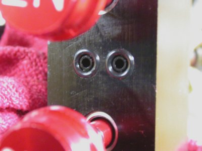
The plate where the buttons come through is flat on the underside. There are two small (< 1/4") depressions in the face of the opposing block with holes in the center. There is an O-ring in each "depression" and the plate is tightened up on them to seal. As I was having problems with it and wasn't sure if the correct O-rings were being used, I ordered replacements straight from Kurt. I installed the "proper" O-rings and thought all was good. Upon firing up the compressor, to my horror, the rush of air out of the seam had doubled or tripled and now the draw bar does not even try to function.
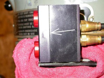

aircontrol02.JPG


I've tried a couple of different sizes of O-ring with little success so now I'm at a bit of a loss. The plate loose "flat" but it wouldn't take much warp in it to make a seal impossible. I'm thinking about taking the plate off and facing it with the mill but I'd like to get second opinions before I start cutting into anything.

Thanks,

-Ron
 
I've seen that happen with many split construction air devices. You might be able to lap the flat side, if it's not flat. If it is, it's the other side, and if you mill or lap it to reduce the depth of the O-ring c'bore, that increases the crush and might solve the problem as well.
 
Curious?? was this a slow ongoing problem, did It just happen over night? I have been there with
-0- rings there are touchy little things. As far as the proper ones, I cant count how many parts I
bought, right box, wrong part. Spark plug junk out of the box. This happens in industry maybe the
stock boy. who knows anyways I still think its wrong 0 rings. Metric / SAE theres zillions of styles.
Myself I would just buy a mixed dozen, they are cheap enough. Hard to beleive its the surfaces unless
you have midnight gremlins. Crush as Tony said,, why not try a paralell over it and see whats going on.(over rings)
Times when too fat will not work or Too skinny theres blow by** I will look for my 0 ring bible book.
 
I've seen that happen with many split construction air devices. You might be able to lap the flat side, if it's not flat. If it is, it's the other side, and if you mill or lap it to reduce the depth of the O-ring c'bore, that increases the crush and might solve the problem as well.

That where I'll probably start. Take it apart again and put a mic to it this time. I can always lap it with a piece of plate glass and some "sand paper" like I do on the heads for my HD cylinder heads. As GK says below though, I do find it hard to believe that the plate would "bend" but this was bought used so anything is possible. All in all I'd have to say that this is a really poor design, JMHO, as I can think of a dozen ways to make it so that it was less prone to this kind of air leak. I suppose those changes would also raise the costs though.... (Damn the "bean counters"!)

Curious?? was this a slow ongoing problem, did It just happen over night? I have been there with
-0- rings there are touchy little things. As far as the proper ones, I cant count how many parts I
bought, right box, wrong part. Spark plug junk out of the box. This happens in industry maybe the
stock boy. who knows anyways I still think its wrong 0 rings. Metric / SAE theres zillions of styles.
Myself I would just buy a mixed dozen, they are cheap enough. Hard to beleive its the surfaces unless
you have midnight gremlins. Crush as Tony said,, why not try a paralell over it and see whats going on.(over rings)
Times when too fat will not work or Too skinny theres blow by** I will look for my 0 ring bible book.

As above, this was bought "used" and was having a "bit of trouble" since I first put air to it. I suppose I didn't notice it as much because there were other troubles with the air system in that one of the bowls for the regulator/filter/oiler was cracked and losing pressure as well as some leaks on the head itself. Fixed the bowl on the regulator and all of a sudden everything else had to deal with more pressure. That's where problems really started to show their heads. I'll be looking hard at the O-rings, again, as well (with my 3x "readers"! :biggrin:)

I'll pull it apart and let you guys know what I find.

Thanks,

-Ron
 
Go to HF and get an Oring selection. Has a zillion different sizes so you should find at least one that is suitable. I would lap the pieces on a piece of glass with some Blue to see if they are truly warped before milling. Too much crush causes O-rings to slip out of the groove and leak too. If you have a regulator, I would slowly up the pressure to see what PSI it starts leaking at. That will go a long way to diagnosing why you are having an issue. Some oring systems are only designed for lower pressures and you may be exceeding the limits with line pressure from your compressor. The oiler is a really good idea though, it will help pistons, rings and O-rings last much longer and reduce rust from wet air.

Bob

I hadn't thought of HF for the O-rings. I did stop by the local True Value Hardware and found similar ones, but in metric, to try out. They seem a hair thicker than the ones I'm using.

I did run the face plate across a flat surface just to see if there was any obvious warp but from that impromptu test it looks might flat. Still going to do quite a bit measuring and trying other things before I try lapping or milling. Here's the pics of what is going on under the cover:

aircontrol03.JPG

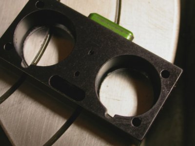
The back side of the face plate. The two little slanted holes are for actuating the green "safety" button.

aircontrol04.JPG

Here's the O-rings nestled in their donut holes. There is a little space on the ID but I would think that is taken up by the "squish".

Will be working on it some more tomorrow.

-Ron
 
You haven't had it apart where the dial is have you? One reason I ask is that there is a check ball to prevent air leakage.
 
Ron,

I would suspect there should be a gasket between the two plates because there is no way two aluminum plates like that are going to seal compressed air. Try a thin gasket with clearance holes around the O-Rings and a little RTV for good measure. You could also just use RTV if you assemble it with the screws finger tight, let it set up over night and then tighten them down.

Tom
 
You haven't had it apart where the dial is have you? One reason I ask is that there is a check ball to prevent air leakage.

The small numbered dial on the head itself? Yes, I did have that apart. Almost lost the check ball, did lose the spring and had to make a new one. :banghead: It's a ***** finding stuff that small on a rough shop floor when you have to use reading glasses!

Ron,

I would suspect there should be a gasket between the two plates because there is no way two aluminum plates like that are going to seal compressed air. Try a thin gasket with clearance holes around the O-Rings and a little RTV for good measure. You could also just use RTV if you assemble it with the screws finger tight, let it set up over night and then tighten them down.

Tom

I checked the parts diagrams from Kurt before tearing in to this thing. Nope, no gaskets, just those two O-rings. As I've said earlier, I think the design itself leaves a bit to be desired. That being said, I have made some headway in getting this thing sealed back up. I did get the two O-rings in the picture to seal fairly well but I was still getting a lot of air coming out of the seam. Further investigation found that the O-rings on the "safety" button (the green thing on the side) were getting pretty beat up from direct contact with the spring for the button (design again :rolleyes:). Replacing those two seals have stopped the air flow while the system is at rest. By design though when you press in the "safety" you'll get a blast of air out of the seam as those seals move to re-direct the air.

I'm still having trouble with the system as a whole but the problem (I think) has "moved" on to the head itself as I hear too much air escaping up there. It's also a pain to work on being 8.5' in the air, above the lights, so it's dim, and me standing on a milk crate or step ladder. Woohoo! Lots of fun. :rolleyes: Have I mentioned I hate working on air systems probably as much as I do with water (plumbing, roofs, windows, etc.)? :cussing:

Thanks guys,

-Ron
 
The small numbered dial on the head itself? Yes, I did have that apart. Almost lost the check ball, did lose the spring and had to make a new one. :banghead: It's a ***** finding stuff that small on a rough shop floor when you have to use reading glasses!


I checked the parts diagrams from Kurt before tearing in to this thing. Nope, no gaskets, just those two O-rings. As I've said earlier, I think the design itself leaves a bit to be desired. That being said, I have made some headway in getting this thing sealed back up. I did get the two O-rings in the picture to seal fairly well but I was still getting a lot of air coming out of the seam. Further investigation found that the O-rings on the "safety" button (the green thing on the side) were getting pretty beat up from direct contact with the spring for the button (design again :rolleyes:). Replacing those two seals have stopped the air flow while the system is at rest. By design though when you press in the "safety" you'll get a blast of air out of the seam as those seals move to re-direct the air.

I'm still having trouble with the system as a whole but the problem (I think) has "moved" on to the head itself as I hear too much air escaping up there. It's also a pain to work on being 8.5' in the air, above the lights, so it's dim, and me standing on a milk crate or step ladder. Woohoo! Lots of fun. :rolleyes: Have I mentioned I hate working on air systems probably as much as I do with water (plumbing, roofs, windows, etc.)? :cussing:

Thanks guys,

-Ron

I'm trying to remember back from when I was working (now on disability) but all of the mills in the Toolroom were retrofitted with the Kurt power drawbars. I don't ever remember any air leaking out unless you pushed the green button, and with that, it was just a short blast around the green button itself. I've had them apart a few times and you are correct, there is no gasket involved between the top and bottom plate. When you say that you had "to make" another spring, I'm wondering if the spring you put back in doesn't have enough tension to it. From what I remember (TRYING to remember) is that the spring that was in there was actually fairly stiff. By that I am comparing it to ....say a ballpoint pen spring. I'm betting that you aren't getting a good enough seal between the checkball and housing. Also on the dial, do you have it set to the max?

If I had one, I'd tear into it to help you out, but unfortunately I don't have one yet and just running on memory.:think1:
 
Back
Top