Problem With Grizzly Rotary Table

Fredb80

Registered
Registered
Joined
Feb 1, 2016
Messages
3
Good afternoon,
First post. (I am relatively new to this whole metal thing). The subject is the Grizzly H7527 rotary table. I bought one and the first thing I found wrong was the backlash. One full turn of the wheel. Yes. Also, I tried installing one of the indexing dividing plates. I found that there was no way that the indexing pin would extend inward so as to go into any of the holes. Grizzly tech support was very good at answering my query and they sent me a new crank handle with indexing pin but it was the same problem. So they had me send it all back and in one day I received a brand new unit.

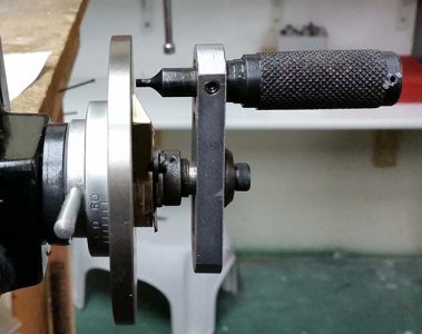
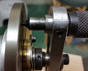
Below is a picture of the whole unit. As well as two pictures showing how the indexing pin doesn't reach the dividing plate. I decided to ask for help here because if I asked Grizzly tech again with the same problem on a new unit they would think .... well I don't know what!

I assembled the dividing plate unit as instructed in the manual on page 14. Here they are in shortened form:

1. Remove the crank handle cap screw and special washer. (check)
2. Remove the handwheel and key from the shaft. Tape the key to the handwheel for safe keeping. (check)
3.Insert the dividing plate, counter bores facing out, and secure it with the provided screws. (check)
4. Place the sector arm assembly over the shaft Figure 14). (check)
5. Slide the sector arm spring into the slot on the shaft to hold the sector arms tight against the dividing plate. (check)
6. Install the crank handle with the indexing pin and secure it with the special washer and cap screw (see Figure 16). (check) Note, - The crank handle slot adjusts so the indexing pin sits directly above the hole circle chosen. To ease installation, place the pin in the desired hole circle, then tighten the cap screw. (Unable to do this as the pin would not reach the dividing plate).

My problem is that the flattened portion of the shaft over which the crank handle slides only allows the crank to go so far inward. One can see that in the pictures.

Now then I searched all over the place and could not find any occurrance of this problem with this unit. So, I have finally reached the conclusion that it is all my fault. Somehow!

Any and all responses are welcome, particularly from those with the same unit.
Thanks for listening!

fred
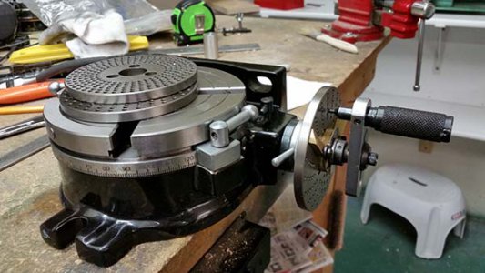
H7527 Full view 600x338.jpg

H7527-01 600x450.jpg

H7527-03 600x476.jpg
PS: Grizzly & Grizzly Tech was great and I will buy from them again!
 
I don't have a dividing head, just a rotary table but... maybe you're looking at this the wrong way. If you're certain the pin won't go in any further, maybe the dividing plate needs to come out further. Possibly it's supposed to have a spacer behind it?
 
Is it possible to loosen the set screw and move the handle in farther? Kinda looks like what needs to happen there.
 
I don't have a dividing head, just a rotary table but... maybe you're looking at this the wrong way. If you're certain the pin won't go in any further, maybe the dividing plate needs to come out further. Possibly it's supposed to have a spacer behind it?

With the amount of threads showing on the shaft that would was my first thought as well.

-Ron
 
I just took a look at my little 4" griz rotary table/ dividing head and it seems to have the same handle.
The slotted handle piece should slip over the two flats on the shaft further than I see in your pics. Is it possible that
the handle is not seating fully on the main divider shaft. Secondly, possibly the detent on the index pin knob seems
to be pulled away from the slotted handle, almost like it hasn't fully sprung forward enough. I know that I'm comparing two
different dividing tables but the handle/crank assemblies look almost exactly alike and I think should work the same.
I have never used mine for anything other than a crude rotary table, but when I pulled out the parts for the dividing head
assembly, it looks like the previous owner might have added a slot in the knob so as to be able to hold the pin away
from the dividing plate for adjustment?? Is the slot in the crank seated over the flats on the shaft that drives the gear?

I'm probably telling you what you have already checked out, in which case I apologize.
My table and divider assembly came without any instructions, nor do any seem to be available from Grizzly.
They do have a parts list on line, but this doesn't sh0w anything about how this thing is supposed to work.

CHuck the very grumpy old guy
 
Hmmmmm.....Try pulling the handle towards you and give it a half turn to see what happens. Maybe it's detented in the out position.
 
First let me thank all of you for the suggestions. In turn let me respond:

Epanzella and Ron: "I don't have a dividing head, just a rotary table but... maybe you're looking at this the wrong way. If you're certain the pin won't go in any further, maybe the dividing plate needs to come out further. Possibly it's supposed to have a spacer behind it?"

Me: The problem with that is that there is a groove that lays just in front of the Sector Arm into which the spring fits to hold it in place. If a spacer were put behind the dividing head it would come forward and the spring would no longer have a groove in which to lock. In this pic you can just see the groove for the spring clip.
(See the pic titled H7527-01 600x450.jpg)

JimDawson and ch2co: "Is it possible to loosen the set screw and move the handle in farther? Kinda looks like what needs to happen there".

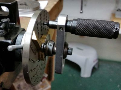
ME: Jim, this is the third crank handle I have had and on the second one I did remove that set screw and tried to tap the handle in. I finally gave it a whack but it didn't move and I was afraid to hit it too hard and perhaps break the spring assembly inside. I measured the shaft of the crank's handle both on the inside (toward the pin) and on the outside and both were about 0.546" so it looks like it should be able to be moved inward. I'll try it again with a brass or alluminium head and see what happens. OK! Jim, I tried to move it in but that was not happening. So I got a brass spacer and drilled it out to fit over the pin. Then tried to remove the handle from the crank arm pounding it outward. It finally worked. When I got it out, I could measure it accurately and the hole in the crank was 0.549. The pin to fit through it was a little variable but from 0.551 to 0.553. And there was a lot of paint on it. So I took some 500 grit and cleaned the hole out and some 220 grit wet/dry and worked on the pin itself. I cleaned it up and found a burr about 2/3 the way up. So I kept at it till rounded and use a little file on the inside edge where it was raised up a little. I then put it back in. You know, that thing is a pressed fit and so why they bother with a set screw is beyond me. Perfect fit. See the pic H7527-03 600x476.jpg and compare it to this one.
[insert pic]

final pin pic 600x348.jpg

Now everything works! And thanks to the membership here. You will probably here from me again!! I'll keep monitoring everything to get ideas!
fred
 
Good afternoon,
First post. (I am relatively new to this whole metal thing). The subject is the Grizzly H7527 rotary table. I bought one and the first thing I found wrong was the backlash. One full turn of the wheel. Yes. Also, I tried installing one of the indexing dividing plates. I found that there was no way that the indexing pin would extend inward so as to go into any of the holes. Grizzly tech support was very good at answering my query and they sent me a new crank handle with indexing pin but it was the same problem. So they had me send it all back and in one day I received a brand new unit.

Below is a picture of the whole unit. As well as two pictures showing how the indexing pin doesn't reach the dividing plate. I decided to ask for help here because if I asked Grizzly tech again with the same problem on a new unit they would think .... well I don't know what!

I assembled the dividing plate unit as instructed in the manual on page 14. Here they are in shortened form:

1. Remove the crank handle cap screw and special washer. (check)
2. Remove the handwheel and key from the shaft. Tape the key to the handwheel for safe keeping. (check)
3.Insert the dividing plate, counter bores facing out, and secure it with the provided screws. (check)
4. Place the sector arm assembly over the shaft Figure 14). (check)
5. Slide the sector arm spring into the slot on the shaft to hold the sector arms tight against the dividing plate. (check)
6. Install the crank handle with the indexing pin and secure it with the special washer and cap screw (see Figure 16). (check) Note, - The crank handle slot adjusts so the indexing pin sits directly above the hole circle chosen. To ease installation, place the pin in the desired hole circle, then tighten the cap screw. (Unable to do this as the pin would not reach the dividing plate).

My problem is that the flattened portion of the shaft over which the crank handle slides only allows the crank to go so far inward. One can see that in the pictures.

Now then I searched all over the place and could not find any occurrance of this problem with this unit. So, I have finally reached the conclusion that it is all my fault. Somehow!

Any and all responses are welcome, particularly from those with the same unit.
Thanks for listening!

fred
View attachment 121056

View attachment 121057

View attachment 121058
PS: Grizzly & Grizzly Tech was great and I will buy from them again!


Fred,I have the same rotary table. For starters the backlash you have is not important.As long as you turn the table in the same direction each time.I had the same problem as you with the pin not extending far enough. Loosen the set screw on the shaft and the pin will extend out more.
Lock the turntable lightly,just enough to keep it from moving. If you lock it tight the table may move a bit.I found that flipping the lever down with almost no down pressure is enough to hold the turntable and does not effect any movement.

mike
 
Back
Top