- Joined
- Jun 10, 2019
- Messages
- 534
If you have the PW Tig225, then you know the cooling fans are ridiculously loud. They are also on all the time (vs. on-demand) which is the real kicker. Decided to do something about it.
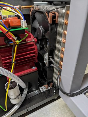
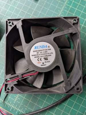
The PW has 2 fans which pull air in from the rear. 24v, 120mm x 38mm deep. Both fans pull air in from the back and thru a tunnel lined with heat-sink fins. I couldn't find anything on the web for the exact model fan; this was the closest match I could find: link. Given the CFM and wattage of the fan I did find specs for, I'm guessing that the PW fans are at least 120-140cfm. This means you do not want your usual or cheaper-brand "quiet" PC fans - these will not push enough air.
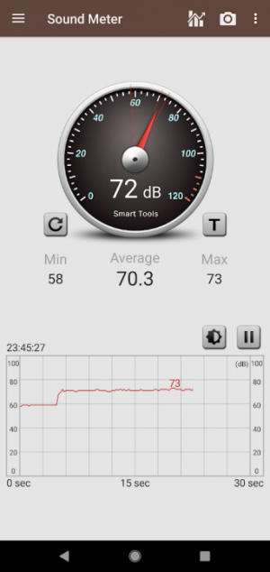
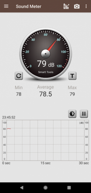
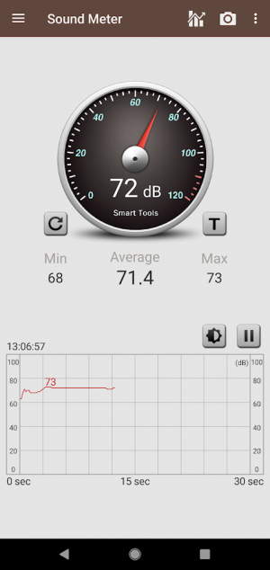
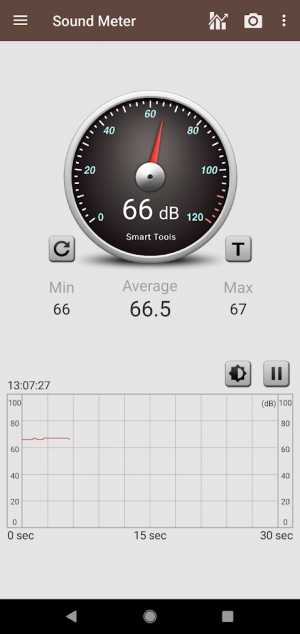
My phone's sound meter shows about 72dB 2 feet from the rear, 66dB 2 feet from the front.
The fan I settled on is the Noctua NF-F12 iPPC-24V-3000 (link). It is 120cfm and designed for pressure applications (radiators and heatsinks). They are rated at 42db (fairly loud compared to the usual "quiet" fans) and can be speed controlled via PWM. For now I decided to run w/o PWM.
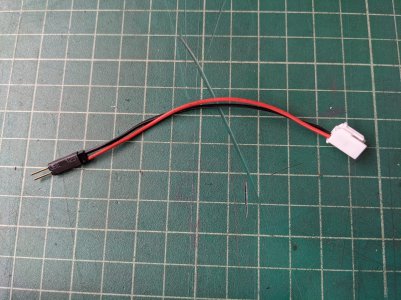
The swap is pretty straight-forward. Besides the fans, I bough new plugs to avoid cutting the original fan wiring (Plug and Pins). I couldn't find a male plug to match the Noctua's 4-pin connector (they do exist, just couldn't find a a vendor), so I cobbled together a solution using standard PCB header pins for now.
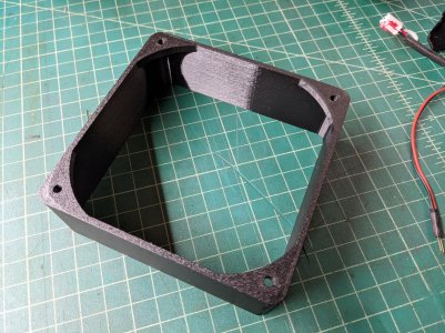
I also designed & 3D printed a new fan duct. The Noctua fans are 25mm deep, so a deeper air duct is needed to keep the airflow directed thru the heat-sink tunnel. Model can be found here: link.
Install Tips
Remove all screws around the top and sides of the sheet metal cover. Remove the 4 feet but do not remove any other bolts on the bottom of the case. There is a ground strap under the top of the case which also has to be removed. Then the cover will come off. You should also remove 4 screws (two on the top, two on the side) which attach the back plate to the frame. This is needed to get a little clearance so you can sneak the fans out. The hardest part is removing the silastic on the fan plugs. You really want to take your time to scrape off what you can and slowly/gently ply the plug off the header. The plug's lever/tab will also likely be glued to the header - some gentle prying and scraping will get it loosened up.
Final Result
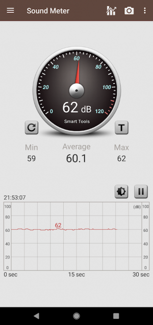
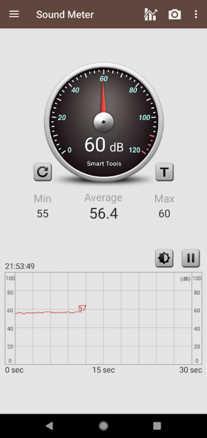
~60dB rear, 56dB front. Although still noisy, it's a significant drop.
That said: I'm not done yet.
I'm going to make a duct for the top fan. The original fan rested right against the top heat sink tunnel so no duct was needed. The new fan is 13mm shallower, so I may print a 13mm thick version of the bottom duct.
I also plan on adding a thermostatic control, but first I need to do some testing to get an idea of internal temps so I can figure out thresholds. A more thorough approach would be also spin up when torch is on. This would require a custom solution (ie. arduino or similar). But spinning down to 25-50% will make this unit pretty quiet. I'll resurrect the thread if/when I get to it.
And a bonus
I was never a fan of the cheap ground clamp or length (10'). When I went to upgrade some bits, I realized that the ground was worse than I expected. The wire measures as 4gauge which is technically too small for a DINSE 35-50 (and pushing it for the max amperage of the PW). I was able to pull the wire out of the DINSE connector without much effort. The DINSE set-screw was turned in so far that it was no longer engaged with the threads. Yikes.
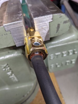
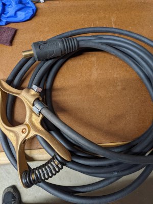
I bought a quality 25', 2gauge wire (link) and a Tweco 300a clamp. Made some heavier copper bushings for the DINSE and clamp out of copper pipe. Much much better. The Tweco takes some serious muscle to open...should have Popeye forearms by spring.
The PW has 2 fans which pull air in from the rear. 24v, 120mm x 38mm deep. Both fans pull air in from the back and thru a tunnel lined with heat-sink fins. I couldn't find anything on the web for the exact model fan; this was the closest match I could find: link. Given the CFM and wattage of the fan I did find specs for, I'm guessing that the PW fans are at least 120-140cfm. This means you do not want your usual or cheaper-brand "quiet" PC fans - these will not push enough air.

My phone's sound meter shows about 72dB 2 feet from the rear, 66dB 2 feet from the front.


The fan I settled on is the Noctua NF-F12 iPPC-24V-3000 (link). It is 120cfm and designed for pressure applications (radiators and heatsinks). They are rated at 42db (fairly loud compared to the usual "quiet" fans) and can be speed controlled via PWM. For now I decided to run w/o PWM.
The swap is pretty straight-forward. Besides the fans, I bough new plugs to avoid cutting the original fan wiring (Plug and Pins). I couldn't find a male plug to match the Noctua's 4-pin connector (they do exist, just couldn't find a a vendor), so I cobbled together a solution using standard PCB header pins for now.

I also designed & 3D printed a new fan duct. The Noctua fans are 25mm deep, so a deeper air duct is needed to keep the airflow directed thru the heat-sink tunnel. Model can be found here: link.

Install Tips
Remove all screws around the top and sides of the sheet metal cover. Remove the 4 feet but do not remove any other bolts on the bottom of the case. There is a ground strap under the top of the case which also has to be removed. Then the cover will come off. You should also remove 4 screws (two on the top, two on the side) which attach the back plate to the frame. This is needed to get a little clearance so you can sneak the fans out. The hardest part is removing the silastic on the fan plugs. You really want to take your time to scrape off what you can and slowly/gently ply the plug off the header. The plug's lever/tab will also likely be glued to the header - some gentle prying and scraping will get it loosened up.
Final Result
~60dB rear, 56dB front. Although still noisy, it's a significant drop.


That said: I'm not done yet.

I'm going to make a duct for the top fan. The original fan rested right against the top heat sink tunnel so no duct was needed. The new fan is 13mm shallower, so I may print a 13mm thick version of the bottom duct.
I also plan on adding a thermostatic control, but first I need to do some testing to get an idea of internal temps so I can figure out thresholds. A more thorough approach would be also spin up when torch is on. This would require a custom solution (ie. arduino or similar). But spinning down to 25-50% will make this unit pretty quiet. I'll resurrect the thread if/when I get to it.
And a bonus
I was never a fan of the cheap ground clamp or length (10'). When I went to upgrade some bits, I realized that the ground was worse than I expected. The wire measures as 4gauge which is technically too small for a DINSE 35-50 (and pushing it for the max amperage of the PW). I was able to pull the wire out of the DINSE connector without much effort. The DINSE set-screw was turned in so far that it was no longer engaged with the threads. Yikes.
I bought a quality 25', 2gauge wire (link) and a Tweco 300a clamp. Made some heavier copper bushings for the DINSE and clamp out of copper pipe. Much much better. The Tweco takes some serious muscle to open...should have Popeye forearms by spring.


Last edited:


