Hi
@BCwoods
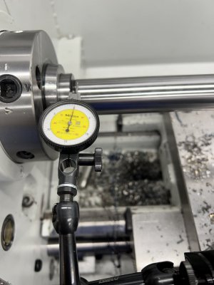
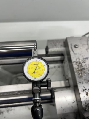
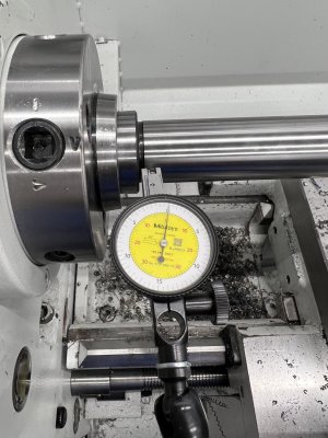
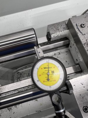
Ok trying to level this lathe. I have a 2in bar 11 in stick out and I have both ends within .0002 but the middle dips in about .0005? All my adjustments are made on the outs
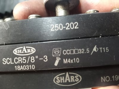
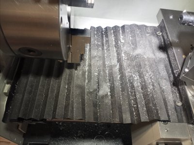
Just noticed your posting and I also have a PM1440GT. Your numbers look really good to me! So I wanted to ask you a couple of questions about your cutting process in the photo of the 0.0005" measured run out....if you can recall. The surface finish on your stock actually looks pretty good for what you did. I have tried small cuts with some carbides that do not look nearly this good. What carbide insert were you using, i.e. tip radius etc.? What were the rotational and feed rates used? What metal were you using? What was the small DOC?
Lastly, where did you get your bellows and how did you attach it.... for catching the cuttings?
Now, and just for fun comments from you and others I offer the following comments: Wrt to the leveling process just a couple of thoughts. Looks like the PM machinist level is quoted to have 0.0005"/10" resolution (radians). A number of cheep Amazon advertised levels claim to have 0.0002"/10" resolution( 0.00002 radians)...if you can believe the adds. It is interesting to look at this resolvable angle in degrees rather than radians. (0.0002/10) * (180 degrees/pi() radians)= 0.00115 degrees. (An extremely small angle). This means of course that with a level like this it is very difficult to use. The lathe must first be fairly level so that the bubble is not just slammed up against one end of the vial .... and may not even be visible.... and almost any simple adjustment just slams it to the other end.
I think the screw feet on the 1440 use a 1/2"-11 tpi thread (an old obsolete English tpi). So turning the screw one turn lifts/lowers that corner by 1/11 inches =0.091". Front to back the leveling screws are spaced at about 15". So turning one foot screw a single turn represents an angle change of 0.091"/15" = 0.00607 radians if the lathe bed were not as stiff as it is. But, still, one might ask, What fraction of a turn of the leveling foot yields the resolution of the level? 0.00002/0.00607=0.00329 turns. So 0.00329 * 360 degree/turn = 1.19 degree. (Most folks like to think of turning an adjustment screw in 1/4 or 1/8 or maybe 1/16th turns of adjustment, but it is possible to make smaller changes if the screw metal friction is not too stick-slip or elastic under the load.) On a really good day it seems that very few of us could ever turn this small 1 degree amount on one of the leveling feet screws....especially when under load and the screw breaks loose. So lets assume that one can not turn the foot screw any less than 5 degrees and this is probably optimistic for many of us. Then 5/1.19 = 4.22 . So the change in the tilt angle of the lathe for a 5 degree foot screw rotation yields 0.00002*4.22~ 0.0008 radians. Clearly the PM level with 0.0005"/10" rotation is even a little over kill. Of course, the lathe bed does not even respond like this simple twisting concept as it is quite stiff, and turning one foot tends to change the load on the others. Hence, you have to turn it more than this simple model would call for in order to change the tilt (twist). (My own experience with this machine was that the bed is so stiff and strong one could turn one corner leveling foot screw until it was completely free from the floor and still the bed twist was not much. My guess is that most of the reason we try to achieve really good lathe bed flatness is distribute the weight so that the lathe does not vibrate (twist and shake) when running.)
The second part of this simple modelling story is even more interesting and is probably failing due to other factors in the process. The lathe cutting tool is usually mounted at the center line of a piece of work. This means that as the lathe bed twists the tool point raises or drops at this point. But this motion at this point is also tangential to the work surface and so if the tool point moves up or down vertically by a small amount it makes an even smaller change in the diameter of the work. Of course this up/down motion depends on the radius of the work piece as one cuts at the circle surface. In your photo you appeared to use a rod of about 1" diameter, but lets assume that it was two inches diameter so that the radius is 1". So for a second, lets assume that the bed twist is bad enough that the tool has dropped down 0.001" at this 1 " distance. This would be an angle of 0.001"/1" or 0.01/10" or 0.115 degrees (About 100 times bigger than the resolution of that Amazon's Machinist level.) But the important question is: What is the cutting error? i.e. the change in the cutting radius of the work piece. A triangle from the center of the work piece has one side of 1" and the other side length of our twist deflection, 0.001". Hence the hypotenuse of this triangle is the root of the sum of the sides squared (1.0^2 +0.001^2)^0.5 = 1.0000005" . (And by the way, this has all made the assumption that one is working at the far end of the lathe bed so that the full twist is coming into play!) So the cutting radius error appears to be only 0.0000005" ~ 0.0127 microns and not even observable by the tools we have!
So how good a level does one really need and why? This simple model would indicate that the machinist level does not need to be all that great!
Also we also might note that this error is much, much smaller than the grain size in any material that we work with so our cutter would need to be sharp enough to cleave grains in two rather than just pulling them out ..... (At the molecular level, no one really understands the cutting process. But there have been lots of academic papers written on the subject.)
Once a lathe is "reasonably" level, other things like material deflection, backlash in the cross feed, cutter grabbing or rubbing, etc. can probably introduce much bigger cutting errors. One of these days I may buy one of those alignment bars that
@davidpbest mentioned!
Dave L.


")