- Joined
- Nov 16, 2012
- Messages
- 5,596
Quick update. Pulled the panel off to see how things were wired and also checked to see if the switches on the operating rod were normally open or normally closed. Turns out, everything works perfectly in our favor.
Just so folks know, I'm setting this thing up so the coolant pump, indicator lamp and work lamp all still run off the original wiring. The input power for the VFD will simply be tapped off the power cord coming into the electrical panel box.
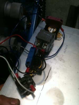
So... Here's a pic of the unadulterated font panel switches. Nothing complicated going on. -Don't panic but I've already rewired it to bypass the stop switch and jog switch. Everything else is left alone. I will later give step-by-step instructions on which wires get jumpered and where. The pictures were taken as I went along -just don't have time today to write it all up. -Takes a while to proofread so nobody gets steered wrong.
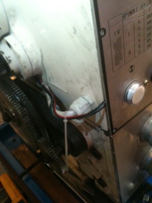
It really is a simple job to do the wiring so I went ahead and did it. For now, I'm just sneaking the two new circuits along some of the outside wiring that leads to the panel box. Later on, I'll find a better way to hide those wires so the front panel can be screwed on tightly again.
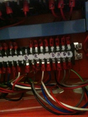
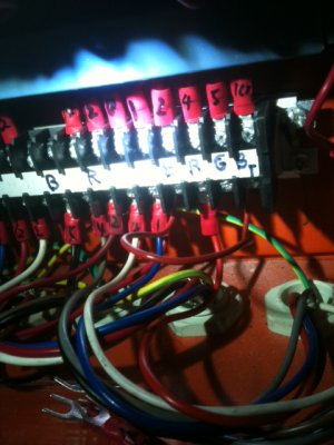
There are two switches underneath the gearbox connected to the operating rod. Four wires run from the switches to the panel block which I marked on the right side as B(lack), R(ed), G(ray) and Br(own). In forward mode, Black and Red are closed. In Reverse Black and Gray are closed. In Neutral, Black and Brown are closed. The catch here is that the circuitry expects to see a closed signal when the unit is in neutral so, a jumper is needed on the terminal block between Black and Gray (second picture of the next two). After that, the other wires are used as the FWD and REV signals into the VFD. And for your edification, the left side wires marked B & R are the foot-brake switch. They are normally open and closed when the foot brake is pressed. The cover switch is in plain view (but not photographed yet) so that's an easy wiring job. The 1st pic just shows the wiring block, the second pic shows the jumper to fool everything into thinking it's still connected to the operating rod.
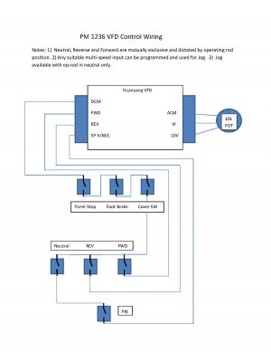
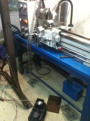
Wanted to do a quick test run to see if the emergency stop still worked along with testing Fwd and Rev. I set things in place (the VFD is on the floor underneath the table and the motor was nearby). Everything worked just fine. The pump and panel light work, E-stop and Fwd/Rev does what it's supposed to. Wires for the jog switch were run but not connected to the VFD. I'm still deciding on how I want it to work although I did figure-out how to program the multi-speed inputs on the VFD.
Again, I will write-up better instructions later on -just want you to know that this wiring job was analyzed and roughed into place in under an hour. This is not a difficult re-work.
More to come but, it's going to take a couple days. -I'm still battling some tough issues at the office these days...
Ray


Just so folks know, I'm setting this thing up so the coolant pump, indicator lamp and work lamp all still run off the original wiring. The input power for the VFD will simply be tapped off the power cord coming into the electrical panel box.
So... Here's a pic of the unadulterated font panel switches. Nothing complicated going on. -Don't panic but I've already rewired it to bypass the stop switch and jog switch. Everything else is left alone. I will later give step-by-step instructions on which wires get jumpered and where. The pictures were taken as I went along -just don't have time today to write it all up. -Takes a while to proofread so nobody gets steered wrong.

It really is a simple job to do the wiring so I went ahead and did it. For now, I'm just sneaking the two new circuits along some of the outside wiring that leads to the panel box. Later on, I'll find a better way to hide those wires so the front panel can be screwed on tightly again.

There are two switches underneath the gearbox connected to the operating rod. Four wires run from the switches to the panel block which I marked on the right side as B(lack), R(ed), G(ray) and Br(own). In forward mode, Black and Red are closed. In Reverse Black and Gray are closed. In Neutral, Black and Brown are closed. The catch here is that the circuitry expects to see a closed signal when the unit is in neutral so, a jumper is needed on the terminal block between Black and Gray (second picture of the next two). After that, the other wires are used as the FWD and REV signals into the VFD. And for your edification, the left side wires marked B & R are the foot-brake switch. They are normally open and closed when the foot brake is pressed. The cover switch is in plain view (but not photographed yet) so that's an easy wiring job. The 1st pic just shows the wiring block, the second pic shows the jumper to fool everything into thinking it's still connected to the operating rod.


Wanted to do a quick test run to see if the emergency stop still worked along with testing Fwd and Rev. I set things in place (the VFD is on the floor underneath the table and the motor was nearby). Everything worked just fine. The pump and panel light work, E-stop and Fwd/Rev does what it's supposed to. Wires for the jog switch were run but not connected to the VFD. I'm still deciding on how I want it to work although I did figure-out how to program the multi-speed inputs on the VFD.

Again, I will write-up better instructions later on -just want you to know that this wiring job was analyzed and roughed into place in under an hour. This is not a difficult re-work.
More to come but, it's going to take a couple days. -I'm still battling some tough issues at the office these days...
Ray


