Paul,
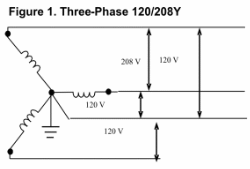
There are two power legs coming to my house, and I have earth ground/neutral to compare them to. Both power lines coming into my house show a voltage of 120 with respect to earth ground/neutral. I stated above that the line to line voltage is measured at 208V. This is only possible if there is a phase angle of 120 degrees between the two power legs with respect to earth ground/neutral.
I agree that absent the reference point of earth ground I would not be able to measure a phase angle between the two power legs, because I would only have those two points to measure. The addition of earth ground to the circuit gives me the third point for my phase angle measurement.
I am not sure where the reference to polarity comes from, I did not use that term in my response. Please clarify the logic you see in my post that states a battery has a phase angle of 180 degrees. I was not trying to state this, and if I did will want to correct my wording. Since a DC circuit is by definition not changing with time there can be no phase angle.
Thanks,
Andrew
I will also note that for my circuits earth ground and neutral are tied together at my panel and represent the same line in any circuit calculations. I will also state that on the 208V supply to my air conditioner there are two hot lines, not the hot line neutral line pair going to my 120V outlets.
The two legs that you are referring to are the start and end winding leads from a transformer. The center tap merely allows a lower voltage to be supplied. Nothing to do with phases. Neutral is a code definition and has nothing to do with legs or transformers. The transformer secondary that serves you is two coils with the end winding of one connected to the start winding of the other. The common wire is called neutral and is grounded in your panel. Electrical safety requirement not electrically necessary.
The distribution transformer that serves you has a center tapped winding that supplies the low and high voltage to you. It is one of three phases. Regardless of what your voltmeter tells you, phase (more correctly phases angle) represents the different times in relation to a reference phase waveform that the voltage begins climbing towards its maximum. This occurs twice in each cycle, once for the positive part of the AC cycle and once during the negative parts of the cycle.
Phase angle is expressed in degrees, but represents time. The time at which the voltage of a phase begins to rise as compared to the preceding phase. One cycle takes 1/60 of a second, 0.016 second. The second phases begins to rise 0.0055 second later, one third of 1/60th of a second. Using phase angle eliminates time as a unit, thus making the phase discussion independent of 50 cycle, 60 cycle or 400 cycle supplies.
If you observe a single phase waveform on an oscilloscope, and place one lead on one leg of the 220 volt buss, and were to observe the positive and negative traces of the neutral and the other 220v leg you will observe that they travel together. On a dual trace scope this will be demonstrated beyond dispute.
The three phases are in reality three separately excited windings, and while the voltage is delivered to the load on three wires (disregard neutral or ground it has nothing to do with the phases) think of each of those legs as a PAIR of wires. each of those legs share a common wire from each of the transformer coils. It is a matter of economy rather that electrical necessity.
In reference to the voltages that you read. I offer no explanation for the difference that you have observed. There is only one phase of the three phases at the distribution transformer available for your service. Therefor only one phase in your house/service. I speak only to the confusion regarding phases.
Perhaps there is a bad ground in your house or service and some leakage between your house and a neighbors is occurring, with those leakage currents resulting in your readings. I would suggest that you wire two light bulbs in series and measure the voltages at the lamps when the series pair is wired to 220. If it is stray grounding or leakage voltages that you are measuring, applying a load and then measuring the voltage would reduce the false readings. Voltmeters are very sensitive and will read a voltage even if it is being supplied through a large resistance, hence very little current. Presenting a large load or resistance would cause enough voltage drop to the milliamp stray voltages to eliminate or vastly reduce them.
If the leakage readings are the result of very high leakage currents, it's time to call in your local electrical utility.
The reference to the battery was to point out that it is impossible to measure phase angles with a voltmeter. Just because the voltages are different does not have anything to do with identifying phases.
In closing, and in the words of Red Green, "It's only temporary unless it works"
paul


