Parabola! (Do doo do do do) Parabola? (do doo doo do)... Hoping for a CAD Master's Interest

Why you gotta brag man?

That's neat!

Don't put your ear in the focus when it's shiny and sunny!

:dancing banana:
OK if you don't point it at the sun. When I was installing those dishes, I did notice an increase in temperature though. Twice a year, the sun would be directly behind the satellite and for about 30 minutes, it would wipe out the satellite signal. I have never seen any permanent degradation of the pick up, probably thanks to the light scattering properties of the paint.

On another point, you might fo well to search for a satellite dish. They were the latest thing in the 1980's but are fairly welll redundant now. Of you weren't 1,000 miles away, I would make a good deal for you on mine. You could get down to the business of cooking rather than constructing.
 
CAD is spiffy, I have it and still occasionally use it. But a few years back(~20), I was tinkering with a "Bucky Ball", a geodesic dome, and wanted a parachute shaped canvas as a cover to spray concrete on. The canvas was to hold the first couple of layers before it became free standing. I built a reduced size experimental frame, a model if you will, and using building paper assembled the form. A brown paper from Home Depot, in a roll 3 feet by something. The brown paper allowed me to "tinker" with shapes that were flared in places and tight in others. I did figure out what I wanted but lost interest before buying the canvas. Yeah, well. . . Such an approach might well allow a CAD shape to be tried before cutting the sheet metal. A lot cheaper. . .

.
 
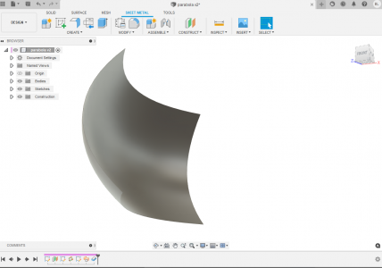
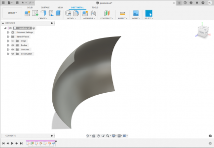
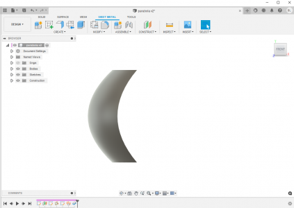
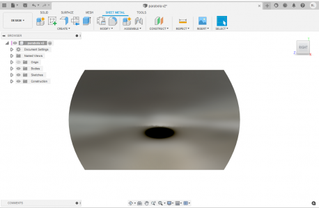
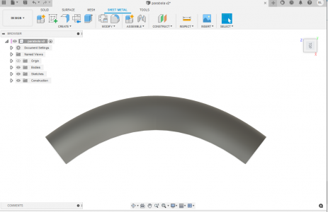
Here is the model. A couple of different views...

parabola.png

parabola 2.png

parabola 3.png
parabola 4.png
parabola 5.png

The issue I'm finding is that in order create this geometry, you have to use the surface modeling, rather than solid modeling. Sheetmetal unfolding (as far as I know) is done with solid models in Fusion. More investigation is required - as the sheetmetal module does want to unfold a parabola like it would polygonal shapes.
 
You can't flatten a surface that is curved in two directions. The surface would have to be stretched or shrunk in at least one direction.

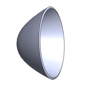
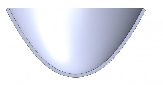
In Solidworks, the creation of a parabolic reflector is easy. I would sketch the parabolic curve using a splined curve and equation linked dimensions and then use an offset to add and second surface to create the thickness to form a solid. I only used five points to create the spline and adding more points would would improve the accuracy of the curve although it should be pretty close as it is. It only took a few minutes. You may be ale to use a similar approach to create a solid model in Fusion
.Parabolic Reflector.JPGParabolic Reflector 2.JPG
 
An Edit to the above. I used a fairly large offset to emphasize the offset. In practice any non zero offset will work.
 
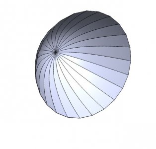
Rather than doing 360º revolved extrusion, I would use a 15º extrusion to create a gore curved in only one direction This gore can be flattened to create a plane surface. 24 of these gores would create a quasi parabolic reflector.
Parabolic Reflector3.JPG
 
Due to the fact that the sun is not a point source (it is about .534 degrees across the sky), the light won't focus to a point. The size of the sun's image is given by: D = mirror-diameter * sin(.267)/sin(a), where .267 is the half-angle of the object (i.e., the sun) and a is the half-angle between the axis of the mirror and a line drawn from the outer edge of the mirror to the focal point. I used this web page as a reference for my calculations.

It is easier to calculate this if we think in terms of the mirror's f-number, given by f/d where f is the focal point and d is the diameter of the lens. I wrote up a little spreadsheet to calculate D (attached) and it shows that you will need a mirror with a fairly low f-number to focus the sun's image into the small spot you want. Something with an f-number around 2. Since your mirror surface won't be a perfectly smooth one, you can be sure that the spot size will be larger than what my spreadsheet tells you.

My spreadsheet doesn't calculate the f-number based on your desired spot size, so you will need to play around with the mirror diameter and f-number to see how D varies.

For a 1-meter (100cm) diameter f-2 mirror, your mirror calculates out to be about 3.125cm deep (this is the value "H" in the spreadsheet). The one thing you need to keep in mind is that the mirror diameter and spot size will completely define the rest of your system dimensions.

I think you will want to achieve something better than 10% accuracy in your mirror shape (or figure). This means you will need to achieve at least a ~1mm dimensional tolerance (probably noticeably better than this).

Given the requirements, it may be difficult to get what you want with your 1-meter mirror. As a fallback, you may want to consider going with a larger mirror and accepting the fact that you're not going to get 100% of the light on your target.
 

Attachments

  • solar mirror calculations.xls
    7.5 KB · Views: 0
The image size is smaller with a shorter focal length The basic lens or mirror equation is 1/f = 1/o +1/i, "f" being focal length, "o" being the object distance, and "i" being the image distance. The object and image sizes are proportional to the object and image distances. The object distance and size of the Sun being somewhat problematic since the size and distance is infinite for all intents and purpose. However, the subtended angle can be used as the ratio of image size to the distance is essentially the subtended angle. That being the case and Homebrewed's value for the angle subtended by the Sun of .534º and the image distance essentially being the focal length, the image size will be approximately one hundredth the focal length. A 1m focal length resulting in a 1 cm image.

A spherical mirror will approximate a parabolic mirror as long as the small angle approximation of sin A = A holds. This obviously subjective because it require a value for the deviation. I drew up a spherical mirror and for rays entering at a distance more than .3*f, 50% of the image would fall outside the focal spot. This would limit the effect diameter of the mirror to .6*f. Past that diameter, a parabolic surface would be needed. A 1m diameter mirror with a focal length of 1m will theoretically concentrate the Sun's radiant power by 10,000 times. According to Wikipedea, the solar flux incident on the Earth's surface is 1.36 kw/sq. m.
 
We're close -- my spreadsheet indicates a spot size of .87cm for a 1m focal length. But I think the almost-inevitable imperfections in the mirror surfaces will blow the spot size up quite a bit more than that (or 1cm for that matter). The gores used to approximate the paraboloid will be an issue no matter what.
 
The width of the widest point on your gores will be the smallest you can get your spot size. All of the parabola calculations are assuming a continuously curved surface not a series of flats.
 
Back
Top