PA From a Pic?

There are a number of CAD programs that can create gears. I know there's a script written for OpenSCAD that can do it. Presumably it allows the user to set the PA along with the tooth count.

For a sightly different approach, McMaster has CAD drawings for many of their parts. Maybe they have drawings you can use for comparison.
 
3d print a gear?
Buy a known PA gear?
Scan, blow up, draw in the pitch circle, measure the flank angle?

Sent from my SM-G715A using Tapatalk
All good ideas. I have a 3D printer at work, but have never created gears or used CAD, so that will take a bit of research and study on my part. I spent at least two hours on Yeggi looking through published gear files and couldn't find anything. Many of the people posting files will say "this is for an XYZ lathe" but not give the DP or PA so it doesn't help much without researching each one.

I got lucky with the second idea. I spent hour or two searching eBay for a 16DP 20PA gear of any kind and didn't find anything remotely affordable (cheaper than a set of gear gauges). Then I remembered I have another lathe....nope, it's all 14 1/2PA.

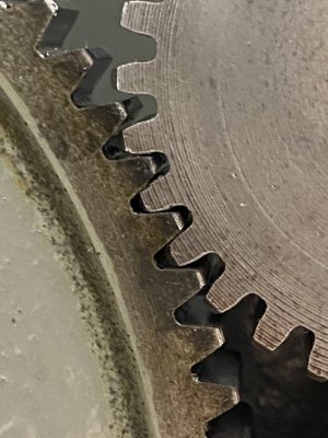
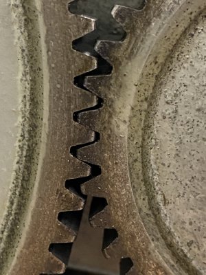
Then I remembered I found a gear in a box of assorted stuff that came with one of my previous lathes. I've been pulling stuff out of that box and my wife has been selling it on eBay because it's been totally random...like huge shaper tool holders, etc. I had set that gear aside to see if it was worth anything...sitting right on top of the work bench not ten feet from my Sheldon. It's a known 16DP 14 1/2PA gear with 32 teeth. First pic is of the 100T gear as it meshes with the 44T gear on the Sheldon, the next pic is with the known 14 1/2PA gear in between them....very obvious difference!

IMG_3286.JPGIMG_3287.JPG
 
There are a number of CAD programs that can create gears. I know there's a script written for OpenSCAD that can do it. Presumably it allows the user to set the PA along with the tooth count.

For a sightly different approach, McMaster has CAD drawings for many of their parts. Maybe they have drawings you can use for comparison.
Thanks...I figured out it's 20PA (post above this) but am interested in being able to create gears in CAD that I can turn into .stl files for 3D printing. I have zero CAD experience, so this is a good opportunity to start I guess!
 
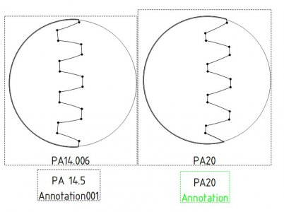
I have drawn (freecad) the DP16 T100 gear 14.5 and 20 TPI. Included are the 1:1 PDF files. You can print the PDF and check your gear.
I have added a file showing the teeth difference in a 1:4 ration
Saw your abovo post and added the freecad file.
There are more CAD programs like Fusion360 that can make gears. All off them have a steep learning curve. You realy have to put the hours into learning.
I learned FreeCad by viewing a YouTube video every evening for a month long and tried to do the same on my computer. I should have done this 10 years ago because 3D is so more productive (for my projects) than 2D.
I 3D print a lot of projects to check the design or as final product. I make my own gears for 10+ years but my large lathe has a couple of 3D printed gears that perform well enough.

PA14,20.jpg
 

Attachments

  • PA14-5.pdf
    244.9 KB · Views: 4
  • PA20.pdf
    235.6 KB · Views: 4
  • PA20&14-5.pdf
    237.9 KB · Views: 3
  • Gear Preasure Angle.FCStd
    940.7 KB · Views: 2
Last edited:
I have cut these but can't post my charts, etc. so here is a link to a full scale chart to identify the metric modules. They are not called pitch in metric.
I can't give this info, it thinks I'm spamming so Search for evolvent gear-identification-template
Here is a handy site for Index plate hole calculator for the RT. Search for bilar Index Plate Calculator
Here is a guide for cutting with the RT dividing plate:

After making one cut:
Assuming you are advancing the material by turning clockwise

Set the back arm against the pin, set the forward arm so it is just past the 13th hole in front of the pin and lock the arms together don't unlock them until the gear is done.

Hold the arms stationary.. Rotate until pin drops into the hole behind the forward hole (1rev + 13)

Make a cut.

Move your arms clockwise until the back arm hits the pin.

Hold the arms stationary. Rotate until pin drops into the hole behind the forward arm.

Make a cut. Repeat til completed
 
Back
Top