- Joined
- Jan 18, 2017
- Messages
- 235
Not trying to resurrect and old topic but I thought this would be better here than in the "What did you make today" since I made it 10 months ago or so.
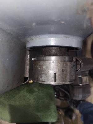
Anyway my machine had a VFD on it when i got and the original owner had made the lower reeves drive sheave stationary(which I would find out later was because it was worn out) about mid range in the sheave. This is what I started with. Worked for a while, then kept breaking. See post 178.

1st attempt to make it work.

Made this brass sleeve to tighten the slop in the heavily worn sheaves. Made the wider key too.

Built a bracket to limit(not downward pressure, just wouldnt allow it to raise) to try and take some of the vibration out I was getting. There is a bearing on the shaft that the bracket rode on.

Needless to say, It didnt fix it. It was a LOT better but it still kept breaking the clutch where I installed that shaft.
Finally got fed up with all the issues with the clutch breaking, wobbling etc and started this project. At least the fix got me through making a new pulley.
If anybody sees anything that looks like its incorrect please let me know. Im self taught so if the tool angle is wrong or the floor is painted the wrong color let me know so I can remedy it.
Im pretty sure it was 4140(which doesnt mean a whole lot to me but thats what they said it was when I bought it) All I know is I couldnt take very heavy cuts on it. It was pretty hard is all I know. Took me a long time to do it.


I tapped the end of the motor shaft for a bolt to hold it all together. I made a "cap" to cover the end of the shaft and allow the bolt to tighten correctly. I had a machine shop cut the key way(lets be honest here, I didnt even know what broaching was until I read on this forum!!) I drilled three holes in the bottom of the "V" groove and tapped for set screws and jam screws. I installed everything and have been using it for approx 10 months or so. Works great. Eliminated all vibration from the bottom. Made the machine super quiet too. Clutch/brake functions as it is suppose to. And the best thing, I had fun, and saved 880 bucks!!!!
Anyway my machine had a VFD on it when i got and the original owner had made the lower reeves drive sheave stationary(which I would find out later was because it was worn out) about mid range in the sheave. This is what I started with. Worked for a while, then kept breaking. See post 178.
1st attempt to make it work.
Made this brass sleeve to tighten the slop in the heavily worn sheaves. Made the wider key too.
Built a bracket to limit(not downward pressure, just wouldnt allow it to raise) to try and take some of the vibration out I was getting. There is a bearing on the shaft that the bracket rode on.
Needless to say, It didnt fix it. It was a LOT better but it still kept breaking the clutch where I installed that shaft.
Finally got fed up with all the issues with the clutch breaking, wobbling etc and started this project. At least the fix got me through making a new pulley.
If anybody sees anything that looks like its incorrect please let me know. Im self taught so if the tool angle is wrong or the floor is painted the wrong color let me know so I can remedy it.
Im pretty sure it was 4140(which doesnt mean a whole lot to me but thats what they said it was when I bought it) All I know is I couldnt take very heavy cuts on it. It was pretty hard is all I know. Took me a long time to do it.
I tapped the end of the motor shaft for a bolt to hold it all together. I made a "cap" to cover the end of the shaft and allow the bolt to tighten correctly. I had a machine shop cut the key way(lets be honest here, I didnt even know what broaching was until I read on this forum!!) I drilled three holes in the bottom of the "V" groove and tapped for set screws and jam screws. I installed everything and have been using it for approx 10 months or so. Works great. Eliminated all vibration from the bottom. Made the machine super quiet too. Clutch/brake functions as it is suppose to. And the best thing, I had fun, and saved 880 bucks!!!!
 and I know only a little more than little
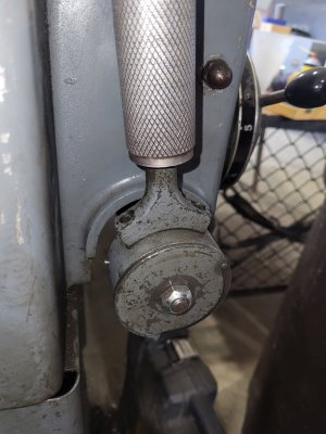
") The cradle lock spring hook(the round part next to the lever and pins with has 2 holes in it) They were 1/8 in diameter but the pins were damaged and so were the holes so I drilled them to 9/64 I also drilled the cover holes as well.
The cradle lock spring hook(the round part next to the lever and pins with has 2 holes in it) They were 1/8 in diameter but the pins were damaged and so were the holes so I drilled them to 9/64 I also drilled the cover holes as well.