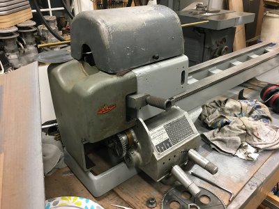
New Caretaker of Two 12” Craftsman Lathes

Well, I'm back at it. I commented earlier about building a stand and a possible under drive countershaft conversion. I located the parts to do the conversion and a complete Craftsman lathe cabinet with drive assembly for a reasonable price, so off I go. It was my Grandfathers, Father’s, and Brothers lathe; time to make it my lathe.

Here’s the cabinet as I got it. Turns out, a variant of the Craftsman lathes were modified and sold into the printing industry in some numbers, which are long since obsolete now so there are some cabinets available in salvage. After a fair drive to retrieve it, here’s how it looked when I got it home, after a drive through the car wash to remove the majority of the grunge. Fairly solid and complete…..
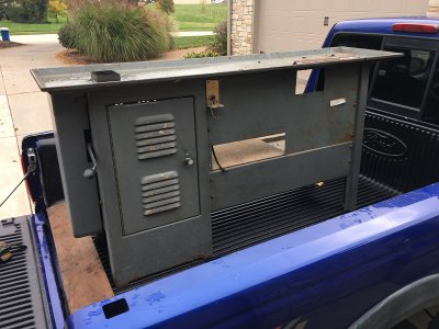
1 Cabinet Home.JPG

…..but the cabinet was for a 54” bed lathe and mine is 42”.
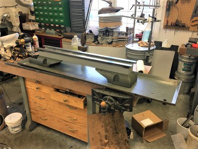
2 Chip Tray Bench.JPG

So I sectioned and reduced the length of the chip pan …..and cut a foot out of the shelf.
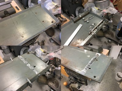
3 Section Pan.jpg

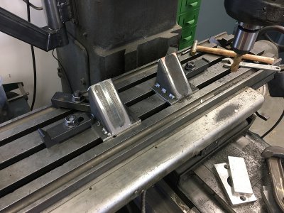
The left pedestal and right upright are 3/16” formed steel and fairly stout. The shelf is formed 16 gauge and only the chip pan on top which was also 16 gauge. To stiffen things up a bit I made and this brace from 1/8” stock and angle that bolts in between them and it really makes a big difference in overall rigidity.
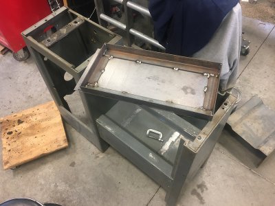
4 Brace.JPG

When reassembled it looked like this and was the correct length for my lathe.
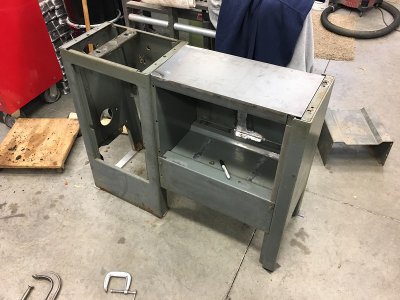
5 Brace.JPG

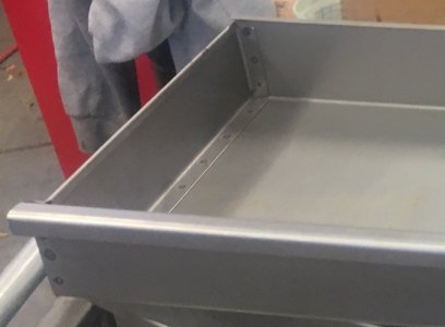
I have lots of tooling and always need storage space. I also have some sheet metal equipment so I decided to make a set of drawers for the cabinet.
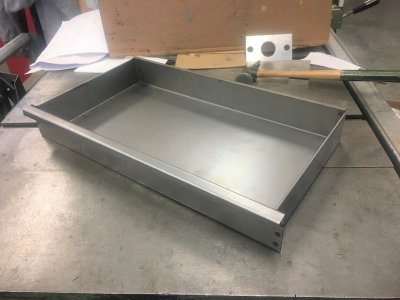
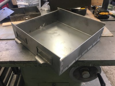
6 Drawer.JPG
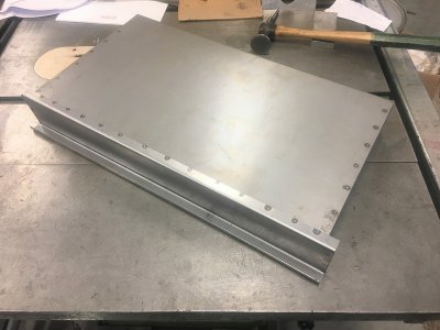
7 Drawer.JPG

The middle four drawers are 20 gauge and slides rated for 100lbs while the bottom drawer is 18 gauge with 500lb slides. The 12” section of chip pan and shelf I removed are in the foreground.
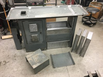
8 Fab Done.JPG

So at this point all the fab on the cabinet was done, it was disassembled, prepped, painted, and reassembled. I had welded some nuts on the cabinet base for leveling feet……could re-decide that for anchors later, but I doubt it.
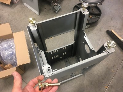
9 Feet.JPG

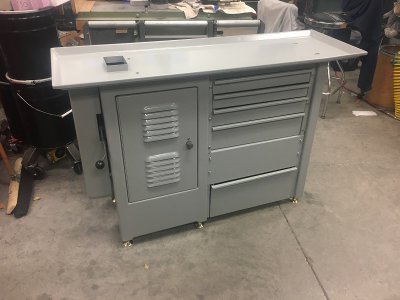
Ready for the lathe which is completely disassembled, painted and waiting for reassembly……….more to come.
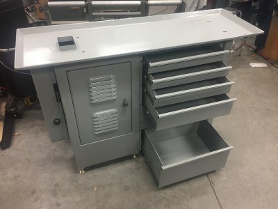
10 Cab Drwr Open.JPG
11 Cabinet.JPG

Best,
Kelly
 
Last edited:
Beautiful work on the cabinet ! Any chance you have pictures of how you made those drawers ?
 
Beautiful work on the cabinet ! Any chance you have pictures of how you made those drawers ?

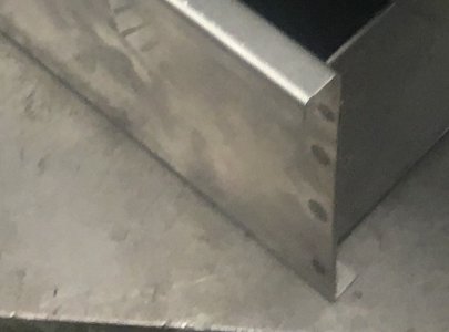
Thanks Alcap. I didn’t take pictures of the piece parts but maybe these will help. Each drawer was four pieces; front, two sides, and bottom/back. They could have been fewer, but making them this way allowed me to make the most efficient use of sheet stock, reach (most) all joints with my spot welder, and accommodate the wider drawer front that covers the ends of the drawer slides. The fronts are also angled to match that of the cabinet pedestal and end cap. I have a 36” jump shear and finger brake.

12 Drwr Front.jpg
13 Side and Bottom.jpg

I said most all above, because I had to stitch weld where the bottom of the deep lower drawer front attaches to the bottom, because as the last assembled joint, though I could reach 12”, I didn’t have the depth on my spot welder tongs.

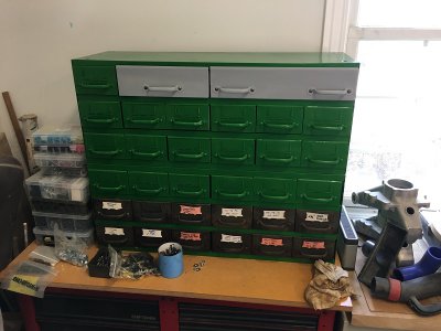
In addition to the lathe, I also got three metal drawer cabinets full of tooling. This one was missing a couple drawers and needed to be cleaned up. So I made a couple wider drawers for it.

14 Refurbed Cabinets.JPG

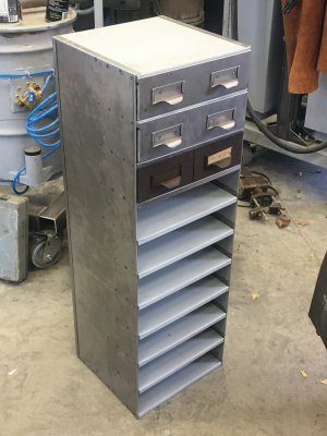
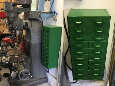
I wanted to use the third drawer cabinet for mill tooling but didn’t have the space, so I made a vertical cabinet, a couple double wide drawers, and used the rest of the drawers from the third cabinet for this wall mounted unit. The drawers were similar construction but only three pieces.

16 Cabinet.JPG
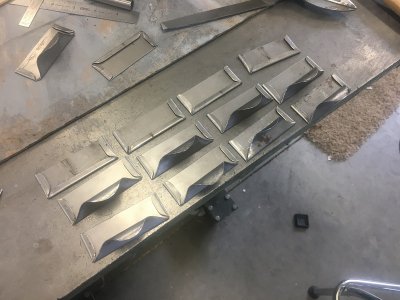
17 Drawer Pulls.JPG
18 Drawer.JPG
19 Vertcal Cab Painted Mounted.jpg
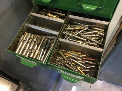
20 End Mills.JPG
Best,
Kelly
 
One word of caution on the left/right mounting position of the lathe is to be sure that the 2-step spindle pulley found only on the four cabinet models (or eight if you count the Craftsman model numbers) is accurately centered over the shouldered hole through the chip pan for the two A-series spindle drive belts to drop through. I can show you what happens if that isn't true.
 
One word of caution on the left/right mounting position of the lathe is to be sure that the 2-step spindle pulley found only on the four cabinet models (or eight if you count the Craftsman model numbers) is accurately centered over the shouldered hole through the chip pan for the two A-series spindle drive belts to drop through. I can show you what happens if that isn't true.

Thanks wa5cab, I did study that quite closely as I was eying up the mods for the underneath drive conversion and hopefully measured properly. We'll know pretty soon. See next post below.

One thing I would like some input on is mounting the lathe to the cabinet. Besides stiffening the cabinet considerably, I was planning leveling the cabinet, then shimming/leveling and rigidly mounting the lathe to the cabinet. I notice the originals had rubber isolators. Wasn't part of my plan. Any reason for them other than noise attenuation?

Best,
Kelly
 
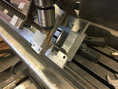
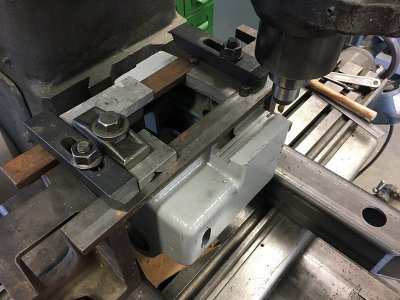
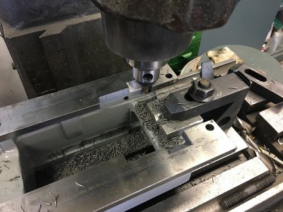
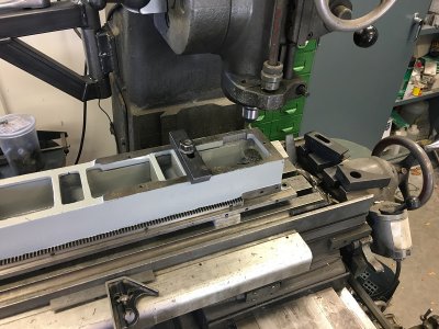
Thanks for the comments fellas. I got after modifying the lathe castings for the underneath drive conversion today. The more contemporary ½” thick way beds had reliefs in the bed for the back gear and belts underneath the headstock and of course the older design bed on my lathe did not. So, I introduced my lathe bed to my Mill. To minimize how much I machined from the bed for the back gear casting, I had to make a couple po—man angle plates…….measure thrice, set up, take a deep breath, and start cutting.

21 PoMan Angle Plates.JPG
22 Back Gear Reliefs.JPG

Both the top and bottom of the lathe bed needed reliefs for the under drive belts.

23 Belt Relief Top.JPG
24 Belt Relief Bottom.JPG

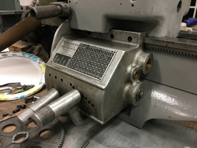
……and then, because I have that aftermarket O’Brien QCGB, I had to slot the bottom of the headstock casting to accommodate the way it mounts and still enable removing it without removing the head stock.

25 Headstock Mod.JPG

I test fit everything and it looks pretty good. When I bought the lathe cabinet, I also got a set of risers/feet and covers. I’ll either modify/weld an addition onto the end cover to accommodate and cover the aftermarket gear box or just cast a new custom one to suit…….but will set that aside for now and get on with the reassembly process and mounting to the cabinet.

26 Test Fit.JPG
27 Test Fit.JPG

Best,
Kelly
 
Last edited:
Kelly,

It only just now dawned on me that both of the lathes that you had were originally 101.07403's, not craftsman equivalents to the Atlas 3900 Series. In order to mount one of them on the under-drive cabinet, you need to replace the 4-step cone pulley on the spindle with the same length one that has a smaller diameter two-groove A-section pulley with both grooves the same diameter. The 4-groove cone pulleys for spindle speed selection are both mounted to the external face of the left wall of the main cabinet and are covered by the rectangular hinged sheet metal cover except whiile changing speeds.

The cutout with the wall around it for passing the two spindle belts through the oil pan is nether long enough nor wide enough for the original 4-step cone pulleys. And I would recommend leaving the back gears and the top cover just as they were.

I would also recommend using the factory rubber seals and mounting arrangement to connect the bed legs to the oil pan. If you don't, you are going to have four constant oil leaks. The factory method works just fine.

I would recommend shimming and and anchoring the six corners in the original manner. Mine is and it has given no trouble in the past almost 40 years. If you must keep the six leveling legs, you need to make six tie-down anchors out of maybe 2" steel channel with about a 1" diameter hole in the center and anchor holes at each end. If you do neither, the lathe will walk all over the place.
 
Back
Top