Need Help Mounting A Dumore Tool Post Grinder To Colchester Lathe

Techie1961

Registered
Registered
Joined
Dec 30, 2015
Messages
131
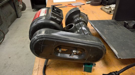
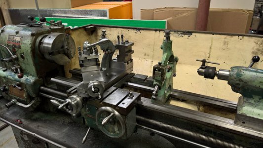
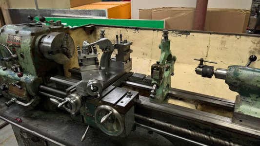
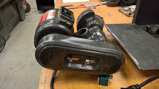
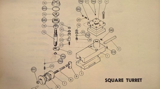
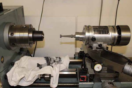
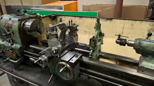
I have a series 57 Dumore tool post grinder that I picked up recently and also fixed up a bit. Now comes the task of mounting it to my lathe. The bore in the main housing of the Dumore is 1.5". My lathe has the original rotating tool holder with cam lever on top and four positions. You can see the style in the photo of the lathe. I tried taking it apart to see if by chance, the post was the right size but it's a bit larger at 1.75". It was a pain to take apart and worse to put back so I'm kind of glad that it didn't fit.

Anyone have any ideas on how to mount this thing? Maybe I have to remove the tool slide and build something that can bring it to the correct height.

On a side note, how do you put a QCTP on this lathe? Does it go right over the post that's in the middle of the original tool post?
23079332173_f062576c0e_c.jpg

26481017500_52b5acfabe_c.jpg

23079332173_f062576c0e_c.jpg

23079332173_f062576c0e_c.jpg

26481017500_52b5acfabe_c.jpg
 
Do you have the tool post that comes with the Dumore grinder? If so, make a t-nut for the bottom of it to fit your lathe compound if the supplied t-nut does not fit. If you are missing the post, they are available from Dumore ($$$), or you can make one to fit. Dumore has the parts catalogs on their web site where you can get the part number to order one or just look at the drawing, measure up the Dumore, and just make one. Your existing four position tool post needs to be removed when using the Dumore.
 
Thanks for the reply Bob. The post is missing from the package that I bought but making something isn't the problem. The Colchester seems to not be friendly to change. I should have taken some pictures with the four position off but it seems that it's center post is integral to the tool slide upper. There isn't a T slot at all otherwise it would be fairly simple.

With the four position off, the tool slide is completely flat on top other than a 1.75" solid steel post sticking up. Have a look at the photo from my manual.
26933490342_130b2168f1_c.jpg
 
That there is no T-slot is pretty common. Perhaps you can make an adapter, sleeve or custom nut. Or just pull it apart again, figure out how it all goes together and make up a center bolt that works for the equipment you will mount on the compound.

I have two lathes, neither has a T-slot. I have added a QCTP to each - in both examples I had to completely take the slide apart. On the first lathe, I probably took the compound apart several times to check the fit. After all I was using the lathe to make the new center bolt.
 
Thanks Chipper, I'm kind of leaning towards removing the tool slide completely (two 5/16 nuts) and making something to go on the cross slide. I won't be able to do any angles with it though. The post on the square turret is larger than the hole in the grinder base so I can't really adapt anything up there.
 
Probably not much direct help to your grinder/lathe combination, more of an FYI. This is how I mounted my Themac. The tool post is removed, grinder clamped with a plate in the T-slot. The Themac spindle can adjustably slide on its T-slot rails attached to the motor housing to locate relative to lathe center height. I've seen some people with bigger grinders / smaller lathes remove the compound altogether & make an adapter plate that matches the compound bolt pattern. This limits you to XY-axis movement only vs. angular movement tough, as I think you've indicated.

IMG_0730_edited-1.jpg
 
Mount it by any method that works, you may spend the rest of your life trying to do it "by the book" which was published in 1939.

I am constantly entertained by hobbyists that consider 60 year old books on machine shop practice as the "proper way" .

This is not to disparage but to encourage methods outside of the norm, in other words do whatever it requires to make it work even if it is contrary to conventional practice, close the old book and kick it aside.
 
Thanks for the comments wreck. I suppose that if you knew me, you would know that I am about as much NOT by the book as anyone can be. :) I live and play outside the box.:D I'm also a tool and die maker rather than a hobbyist.

I don't have a lot of time on lathes but instead on mills, surface grinders, etc. I was hoping that I was missing something on how these usually mount up since I haven't ever used one. I think that that tool slide must be a special for Colchester only and even if I want to put a QCTP on it, I'll need something custom. Thanks again for taking the time to respond.
 
Is there enough material around the bore on the tool post grinder to bore it out to fit the tool post?
The Colchester Student I had looks identical but had a conventional compound with T-slot.
Removing the compound should work but you loose the ability to swing the compound to 5.74 degrees from axial and get a fine in-feed of 10:1, nice feature I've used the few times I've needed the grinder.

Greg
 
If you are a tool and die maker, maybe make a compound top to replace the top half of the Colchester one completely when you want to use the grinder, using the Colchester bottom half for the slide, gib, swivel, and ways. Kind of overkill, though, and it might be slow to change from the grinder to the normal compound top, but it would leave the lathe in original condition and you could use the modified compound motion to grind tapers.
 
Back
Top