This thread is about my PM-1640TL also known as TL-1640 which I received in August, 2021. I had placed the order at PrecisionMatthews.com only weeks earlier. It was ordered with DRO and the taper unit installed.
I was posting to the thread "PM-1660TL" which was started by @erikmannie in June, 2020. He was kind enough to ignore that I was posting about a TL-1640 on a PM-1660TL thread. Another member kindly suggested that I start a tread. Now that I look at the title of @erikmannie 's thread, it is indeed titled "PM-1660TL". So, this thread is the result of following that suggestion.
Try searching for how to start a thread on a site devoted to machining: lot of interesting threads that will be helpful when my lathe is finally operational. In the end, it is quite easy to start a thread here, unlike on some other sites.
So, the machine arrived on a flat bed truck with a fork lift and I took delivery in front of the garage, on the parking pad. After uncrating, initial cleaning, and moving it to its location in the garage. Only a little more cleaning was required. Most of the cleaning was done outside. It had been planned that way because I didn't know what toxic fluids would be finally required. There are many suggestions on the internet. As it turns out, the machine was coated with an easily removable sealant. Nothing nastier than WD-40 was required in most places.
The machine survived it's journey with no visible mishaps. There were only very minor dings, hardly noticeable, really, but of course, I had to touch up the dings before it was moved to its planned location.
I tried every control that I could as an initial check.
The markings on the apron on how to engage the power feed for carriage drive or cross feed drive is counter intuitive, to me anyway. It's bass-ackwards. I'll confirm this after the machine is powered up.
The threading dial indicator, when it is disengaged from the lead screw, interferes with the power and direction handle when the handle is raised.
The cross slide hand wheel was very stiff, requiring both hands to turn it. I followed many suggestions from members here, and the hand wheel became much freer. But I did have to get assistance from Precision Matthews. I was prepared to hold for hours or play phone tag, as when I have to interact with one of my banks. But within minutes I was talking to a real person. He said he knew my problem from my postings here on Hobby-Machinist. He suggested that I look at the mounting of the taper unit to the back of the carriage. It may have shifted during transit. It was good advice and now I have a cross slide hand wheel that can be turned by one hand, and more importantly, I feel comfortable that I can apply power to the cross slide.
My garage floor slopes a bit and it required a half inch shim at the tail stock end for it to be leveled. All six feet are sitting on a single concrete slab. The goal of leveling is to take out the twist in the bed. The trick to leveling is to use a high grade machinist level that has a calibration or fine adjustment for itself and follow the level manufacturer's instructions on how to use the level. Then plan on iterating the leveling many times. After all, there are six feet and they all interact to twist the bed. During my final iteration, a very small turn of the adjusting bolt of about 10 degrees made a noticeable difference in the bubble. Ten degrees is about a minute and a half on the face of a mechanical watch. The rounded end of the adjusting bolt sits in a dimple of a cast iron (I am guessing) disk. The disk itself has four protruding portions that interfaces with the concrete. I am betting that after the machine vibrates, in days or in weeks, there will be settling and the machine twist will have to be adjusted again.
Now the machine looks almost like PM's advertisement photo, including even the impossible to read directions of the threading dial from a standing position.

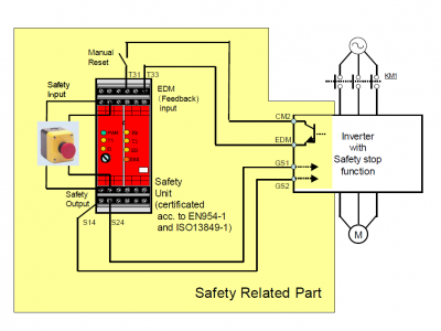
I am at a point now of integrating the Hitachi WJ200-075LF which was also purchased form Precision Matthews with the PM-1640TL. I posted my understanding of the electrical aspects of the lathe, using the supplied electrical diagrams. My main concern is to preserve the safety circuits of the original lathe. My goal is to make as few modifications as possible and if wires are removed from the circuit, to leave them in place or near the original locations so that all can be undone by some other person at a later time.
I posted several observations about the safety circuits at the thread "PM-1660TL" and was about to post some conclusions there. Thereafter, postings about my PM-1640TL TL-1640 will continue in this thread.
I was posting to the thread "PM-1660TL" which was started by @erikmannie in June, 2020. He was kind enough to ignore that I was posting about a TL-1640 on a PM-1660TL thread. Another member kindly suggested that I start a tread. Now that I look at the title of @erikmannie 's thread, it is indeed titled "PM-1660TL". So, this thread is the result of following that suggestion.
Try searching for how to start a thread on a site devoted to machining: lot of interesting threads that will be helpful when my lathe is finally operational. In the end, it is quite easy to start a thread here, unlike on some other sites.
So, the machine arrived on a flat bed truck with a fork lift and I took delivery in front of the garage, on the parking pad. After uncrating, initial cleaning, and moving it to its location in the garage. Only a little more cleaning was required. Most of the cleaning was done outside. It had been planned that way because I didn't know what toxic fluids would be finally required. There are many suggestions on the internet. As it turns out, the machine was coated with an easily removable sealant. Nothing nastier than WD-40 was required in most places.
The machine survived it's journey with no visible mishaps. There were only very minor dings, hardly noticeable, really, but of course, I had to touch up the dings before it was moved to its planned location.
I tried every control that I could as an initial check.
The markings on the apron on how to engage the power feed for carriage drive or cross feed drive is counter intuitive, to me anyway. It's bass-ackwards. I'll confirm this after the machine is powered up.
The threading dial indicator, when it is disengaged from the lead screw, interferes with the power and direction handle when the handle is raised.
The cross slide hand wheel was very stiff, requiring both hands to turn it. I followed many suggestions from members here, and the hand wheel became much freer. But I did have to get assistance from Precision Matthews. I was prepared to hold for hours or play phone tag, as when I have to interact with one of my banks. But within minutes I was talking to a real person. He said he knew my problem from my postings here on Hobby-Machinist. He suggested that I look at the mounting of the taper unit to the back of the carriage. It may have shifted during transit. It was good advice and now I have a cross slide hand wheel that can be turned by one hand, and more importantly, I feel comfortable that I can apply power to the cross slide.
My garage floor slopes a bit and it required a half inch shim at the tail stock end for it to be leveled. All six feet are sitting on a single concrete slab. The goal of leveling is to take out the twist in the bed. The trick to leveling is to use a high grade machinist level that has a calibration or fine adjustment for itself and follow the level manufacturer's instructions on how to use the level. Then plan on iterating the leveling many times. After all, there are six feet and they all interact to twist the bed. During my final iteration, a very small turn of the adjusting bolt of about 10 degrees made a noticeable difference in the bubble. Ten degrees is about a minute and a half on the face of a mechanical watch. The rounded end of the adjusting bolt sits in a dimple of a cast iron (I am guessing) disk. The disk itself has four protruding portions that interfaces with the concrete. I am betting that after the machine vibrates, in days or in weeks, there will be settling and the machine twist will have to be adjusted again.
Now the machine looks almost like PM's advertisement photo, including even the impossible to read directions of the threading dial from a standing position.
I am at a point now of integrating the Hitachi WJ200-075LF which was also purchased form Precision Matthews with the PM-1640TL. I posted my understanding of the electrical aspects of the lathe, using the supplied electrical diagrams. My main concern is to preserve the safety circuits of the original lathe. My goal is to make as few modifications as possible and if wires are removed from the circuit, to leave them in place or near the original locations so that all can be undone by some other person at a later time.
I posted several observations about the safety circuits at the thread "PM-1660TL" and was about to post some conclusions there. Thereafter, postings about my PM-1640TL TL-1640 will continue in this thread.