My journey putting a new PM833TV mill in service

IR-JEB

H-M Supporter - Sustaining Member
H-M Platinum Supporter
Joined
Feb 9, 2022
Messages
29
I have been very deficient in posting regarding my PM833TV mill, however my progress was slow.

I have utilized many posts in this group to improve my understanding and knowledge in many areas. I am extremely grateful for those that shared their experiences for others to benefit from. As a result, I will make multiple posts to this thread outlining the process I went through to build a stand, get the mill into my shop which is in a 9-foot-deep basement, putting the mill on the stand, installing the power feed for the X and Z axis, installing the 3 axis DRO a MagXact MX-200M, and a couple of minor tweaks along the process. I hope someone can find value in my posting.

I ordered this mill on February 25, 2022, and it was ready for pickup on March 17th! At the same time I ordered a PM1440GT which had an expected arrival of August, which has been pushed back to mid-October. A recent check has confirmed the lathe is in a container and is on a ship homeward bound! Precision Mathews is an easy day’s drive from my home being just under 225 miles one way. So, my wife and our dog went on a road trip to Precision Mathews to pick the mill up. This was a good opportunity to see the business and meet some of the staff.

We arrived about 11:00 in the morning. Finishing the transaction and loading the mill went off without any issues and they were very prompt. Also got a nice tour of the facility, did not get any pictures outside of my mill waiting for pickup. As expected, the warehouse had a lot of room waiting for incoming shipments. We only meet a handful of people, but they were all very nice and happy to show the facility. They all appeared to have a lot of pride in working at PM.

20220317_113355_std.jpg


Building a stand for the PM833TV while it sits on the trailer in the garage.

I started to work on the stand next as my main support assistant for moving items is my son and he had work priorities and vacation scheduled.

I was lucky to have the mill at my residence and have the time to configure a workable plan for the stand. I settled on building a stand of the following dimensions, 35” wide by 31” deep by 31” high; the chip pan is 38” wide and 34” deep. I constructed the stand utilizing 2 X 2-inch steel box tube top horizontal members and legs with a wall of 3/16” and 1/8” 2 X 2 tube for the rest of the main support. I wanted the base of the mill to sit inside the chip pan, so I raised the mill up on a 2 X 4-inch ¼ inch wall riser to enable the Y axis crank handle to be used without impacting fingers and places the base of the mill approximately 33 1/4“ above the floor with the wheels installed.

I only have a TIG machine for welding, so make sure I have the metal cleaned well prior to welding. Below is a picture of the tube for the stand ready to weld up.

20220409_152553_std.jpg


Below is a picture of the riser block which will sit in the chip pan

20220413_174807_std.jpg


I wanted to test the hole locations in the riser block for proper spacing before drilling the chip pan. I set the mill on the riser and used guide pins to verify a good fit.

20220424_105905_std.jpg


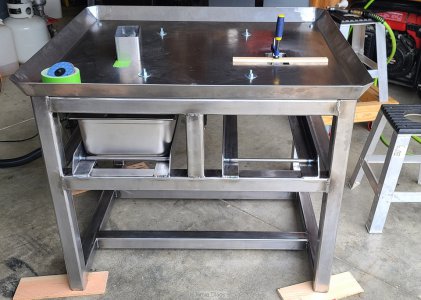
The welding for the main frame went off without any issues. I wanted to add swarf catch pans to this design, so I purchased a couple food service stainless steel steam table pans (12 3/4” X 20 3/4” X 6”) and configured a rack to enable the pans to be slid under the chip pans.

20220421_172731_std.jpg


The frame is getting heavy now, so I had to get help getting it down off the table so I could work on the chip pan. At this point, the stand is 260 pounds which includes the riser.

20220424_151353_std.jpg


I welded in 2 sections of rectangular steel box to the chip pan so the swarf / chips can be pushed or swept into the pans below. I used 3” X 5” X 0.120” rectangle tube just 3 inches long to help direct swarf into the pans below. So far this has been working well.


20220425_180921_std.jpg


20220426_173722_std.jpg


All cleaned up and ready to get it powder coated.

20220427_114548_std.jpg


After powder coating and finally in my basement

20220506_142849_std.jpg
 

Attachments

  • 20220424_151353_std.jpg
    20220424_151353_std.jpg
    533.7 KB · Views: 69
WOW! You did a fantastic job. Congrats.
 
Part 2 - The move into the basement.

When we were able to move the mill into the basement, I decided to make this a practice run for bringing the PM1440GT into the basement so my preparation was much greater than I would have done for just a mill of this size.

In preparation I removed the table to reduce a bit of weight and width. This also enabled a good cleaning of the lead screw, table, and ways and gibs.

20220323_170536_std.jpg


Then with the mill still on the trailer I built a “sled” of sorts to enable the mill to be easily rolled and slid down into the basement. This will be the same sled I will use for the lathe.

20220325_162019_std.jpg


I was able to locate the trailer in a position which enables an easy access to the basement stairs; they are a straight shot through my garage door through a laundry room. I built a ramp of sorts to roll and slide the mill into the basement. Ready for my son to stop over after work.

20220330_172822_std.jpg


I am very comfortable utilizing rope systems to make my life easier as I have previously been qualified in Advanced Rope Rescue and Confined Space Rescue. So, an obvious method of controlling the descent of the mill into the basement was with a rope system(s) for the descent with a safety backup.

20220330_180254_std.jpg


I had the trailer blocked in all 4 corners and the mill rolled on the ramps into the house with only the push from myself with very little effort. From the trailer the rise into the house was about 4 to 5 inches. Sections of ½ inch steel conduit was used for the rollers. New rollers were placed under sled as forward progress was made. This went so well and fast I did not get any pictures until the mill was in the house.

20220330_172844_std.jpg


Now a bit of anxiety while pushing the mill sled over the edge. The anxiety was not warranted as the transition onto the ramps down the stairs went very smoothly. Did wait until the sled was totally on the ramp going down the stairs before getting any additional pictures.

20220330_180154_std.jpg


A guide rope was placed on the sled and my son guided the sled down as I lowered it with the rope descent system.

20220330_180244_std.jpg


Once we neared the bottom of the stairs/ramp we had to lift the front as we prepared to place the sled onto dollies, I had built each dolly with casters rated at 600 pounds per caster. The transfer off the stair ramp is the only spot I will slightly alter for the lathe. I will prepare a means to fasten the first dolly to the front of the sled instead of initially using a floor jack. Using a rescue mini haul system, small block and tackle, the uphill end of the sled was controlled as it transferred from the stairs to a horizontal orientation onto the two dollies.

20220330_180532_std.jpg


20220330_182146_std.jpg


20220330_182407_std.jpg


Setting the mill on the stand.


A 1 ½ ton lever chain hoist was used to lift the mill up onto the stand. I found even with the main lifting point at the circular section of the headstock at the scale marked in degrees with the table all the way back, the mill was still heavy in the front. I counteracted the forward lean by using the mini haul again and connected it from the top anchor point to the front lifting eyes mounted in the front holes. I would guess the mini haul only counteracted 50 to 75 pounds. This enabled the mill to be placed on the stand with the riser under great control without a scratch.

1_154646_std.jpg

Mill ready to lift

2_172417_std.jpg

Ready to roll the stand under the mill
3_172914_std.jpg

On the stand bolted down

4_174007_std.jpg

 
Part 3 - PM833TV power feed installation Align X and Z axis

The installation of the Align power feed units both were very easy to install. I utilized the instructions in the mills owner’s manual with the X-Power-Feed-Installation PDF file both of which are available in the Manuals and Documents tab for the PM833TV.

Link to the manual:

https://www.precisionmatthews.com/wp-content/uploads/2019/11/PM-833TV-5-13-2022-V2.pdf

Link to the X-Power-Feed-Installation PDF:

https://www.precisionmatthews.com/wp-content/uploads/2017/02/X-Power-Feed-Installation.pdf

The main instructions are clearly outlined starting on page 25 of the manual. I would like to highlight when drilling the holes in the replacement gear shaft and extender for the Z axis after the 1st hole is drilled, the roll pin does not have to be fully inserted to maintain the proper alignment to drill the second hole. The shaft and extender still must be separated during the final assembly. I did find the supplied roll pins were very difficult to insert and purchased new roll pins from one of the big box home stores. They inserted as expected providing a good snug fit.

The X axis power feed installation went very quickly. I contacted tech support at Precision Mathews about the installation of the gear to the lead screw. In my installation, the X axis bearings ID race was not proud of the OD race, and this created drag on the leadscrew and a significant backlash for this axis. Tech support did not see or have any issues with the following modification. I purchased a stainless-steel washer, turned the OD to have clearance with the outer race and enlarged the ID of the washer to just fit on the lead screw. The washer was inserted between the bearing and the gear for the power feed. This reduced the drag on the lead screw and improved the backlash.

1_153055_std.jpg

Lead screw with hand wheel removed

2_153114_std.jpg

Shim / washer on the lead screw to offset the gear

3_154552_std.jpg

Power feed gear installed


PM833TV 3 axis DRO installation, MagXact MX-200M

While reviewing the installation instructions for the DRO and dry fitting the scales with the supplied generic brackets, I decided to get some milling experience and make my own brackets for all but the X axis reader head.

The X axis reader head worked well with the supplied bracket. I installed the magnetic scale on the rear of the table and slightly over a ¼ inch below the table’s surface. This was to ensure the vise will not contact the cover when installed for this axis.

1_202436_std.jpg


I added a spacer block around the X axis reader head to permit the rear chip guard could be mounted without resulting in a point for chips to be trapped. The area around the reader head is covered with the scale cover.

2_122912_std.jpg


3_104829_std.jpg


On the Y axis I chose the left side of the mill as viewed from the front for the scale and reader. I configured the reader head bracket to mount to the rear edge of the table and mounted the scale to the base of the mill approximately 1 inch down from the edge. See the pictures for the details in the bracket configuration I utilized.

4_202422_std.jpg


The Z axis was installed on the left side of the column and incorporated the Z axis power feed limit switch and stops. I machined a base for the limit switch to mount close to the column and have a raised section to mount the reader head extension section. I did purchase a section of extrusion from 80/20.net which is a 1.50” X .75" Smooth Surface T-Slotted Profile aluminum extrusion part number 1575. This is the track I mounted the limit switch spring-loaded end stops to. Using this extrusion did require a slight modification to the spring-loaded end stops as they were designed for a wider track. A few minutes on the mill to reduce the guide section which inserts into the track, and they fit perfectly. I also purchased a couple of the series 15 T-nuts in 5/16-18 and an endcap. This track was mounted facing the front of the mill to an aluminum standoff that is made from 1 ¼ X ¾ aluminum rectangle bar stock that is 28” long.

The scale is mounted directly to the column and the gib screws are utilized to obtain the proper alignment.

The limit switch being mounted in this configuration does require the headstock to be at least a few inches above the lower limit switch if a lower adjustment is made. This is due to the reader head extension arm covering the limit switch just prior to switch activation. This has not presented itself as a problem when this is known.

5_164900_std.jpg


6_184517_std.jpg


10b_172912_std.jpg


7_172855_std.jpg


For the scale covers I utilized 1.5" x 1.5" x 0.125" aluminum angle for the Y and Z scales and 2" x 2" x 0.125" aluminum angle with one leg cut down to 1 5/8” on the X axis. The 1 5/8 side is the top and the 2-inch side covers the gaps between the reader head and the spacer block. Where appropriate, I TIG welded end caps of 0.125” aluminum on the scale covers and flattened them out. The scale covers for the X and Y axis are mounted to the threaded scale end caps. The Z axis scale cover is mounted to the standoff that the limit switch track is mounted to.

8_105133_std.jpg

X axis cover

9a_160000_std.jpg

Y axis cover

10_173327_std.jpg

Z axis cover

I elected to mount the DRO unit on the right side of the mill just below the name plate. This location has been comfortable for me. I found the mounting bracket to have excessive play for both pivot points. I drilled them out to have a close fit for a 7/16” socket head cap screw. To enable the joints to pivot, I utilized 4 bronze washers for each bolted connection. The mounting for the DRO display was raised with a stainless steel bushing 0.5“ in length with an outside diameter turned to a 0.860”. This closely matches the bronze washer I used. The standoff bushing was made from scrap 1” stainless bar I had. The bushing gets the socket head cap screws which mount the display to the bracket above the pivot arm. Therefore, enabling the display to be placed in any desired orientation. Two 7/16” large hard washers were placed above and below the DRO mounting plate to provide a bit more support and stability.

11a_103351_std.jpg


11b_103530_std.jpg


11c_103520_std.jpg
 
Tim, The rope setup I configured used the lime yellow rope was the main lowering line. The rope is a 11mm static line, it has a breaking strength just over 8000 pounds. I configured it in a 3 to 1 mechanical advantage and the rope was controlled with the break rack that’s the stainless item with the rope weaving through it. The 3 to 1 system reduces the force on the lower line by a factor of 3 however the line must be feed into the system 3 times faster than the load lowers. The break rack provides great control on the amount of friction with multiple means of increasing or decreasing it. The 3 to 1 utilized the upper (fixed) pulley and another at the load end. The safety the yellow / red line is a single line from the orange webbing at the top with a double prusik belay setup. I utilized for convenience the cable come along to provide a means to release the prusik lock if it became engaged. That is not rescue approved, however. The prusik belay is a method of utilizing two rope loops which are wrapped on the safety line and if tightened the loop will lock on the safety line. In the higher load locations steel carabiners are used to increase the safety margin of the system.

The mini haul that I used to assist in lifting is simply a rope block and tackle. The haul line is run through a prusik to enable it to hold a load without being tended.
 
Thanks for the info.

From the photos it looks like the move went smoothly and it sounds like you were well prepared. Good Job! :encourage:
 
Back
Top