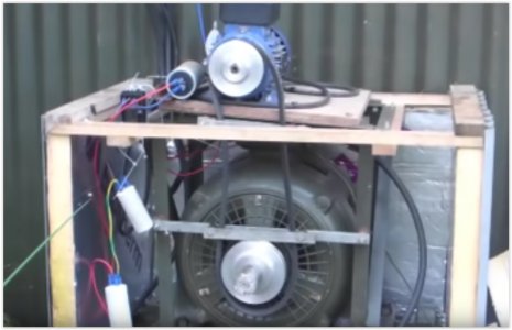
[How do I?] My 2017 Rotary Phase Converter Build

Hum, it looks like it is essentially the same circuit except it uses one hot phase and a neutral going into the idler motor (instead of two hot legs) and the center tapped neural coming out, that makes sense now. As mksj said, the amps are your biggest problem. That chart is for supplied three phase power. You are creating 3 phase power from a single phase 240V source, so that times 40A gives you a total of 9,600 watts. A Horsepower is about 746 watts, so that only gives you around 12 theoretical Hp you can run, including the RPC and assuming you have nothing else to power such as lights etc. The term "generate" is somewhat misleading the idler motor doesn't create any extra power it only transforms the supplied power into the ghost phase. Think of it as a rotary transformer. The energy output can never be greater than the energy input. So with the RPC you can run a 5 hp motor, maybe a 7.5 hp. The RPC system uses up some power running the idler, I think is a little shy of 10% so the system will be around 90% efficient. On the other hand, VFDs are more efficient (I think around 97%), so you'd be able to squeeze out a little more usable energy maybe you could get a10hp. motor running but that would be really pushing it and of course not much else....
 
Hum, it looks like it is essentially the same circuit except it uses one hot phase and a neutral going into the idler motor (instead of two hot legs) and the center tapped neural coming out, that makes sense now. As mksj said, the amps are your biggest problem. That chart is for supplied three phase power. You are creating 3 phase power from a single phase 240V source, so that times 40A gives you a total of 9,600 watts. A Horsepower is about 746 watts, so that only gives you around 12 theoretical Hp you can run, including the RPC and assuming you have nothing else to power such as lights etc. The term "generate" is somewhat misleading the idler motor doesn't create any extra power it only transforms the supplied power into the ghost phase. Think of it as a rotary transformer. The energy output can never be greater than the energy input. So with the RPC you can run a 5 hp motor, maybe a 7.5 hp. The RPC system uses up some power running the idler, I think is a little shy of 10% so the system will be around 90% efficient. On the other hand, VFDs are more efficient (I think around 97%), so you'd be able to squeeze out a little more usable energy maybe you could get a10hp. motor running but that would be really pushing it and of course not much else....
If you look the circuit I posted the Neutral is only used to start the Idle motor, so while starting the Idle gets the full benefit of the (say) 40 AMP's to start a 30HP motor including the Neutral which allows any spare current to flow back to the consumer board while it is in the circuit. Then once started the Neutral is disconnected and the Idle uses the full 40 AMP's to Run the 30HP motor just powering L1 with full 240V power. In the YouTube video's I posted the guy in the UK uses this design to Run a 17.5HP motor, so I am assuming it will work for what I am wanting to achieve. So in this design there are 2 ghost legs L2 & L3
 
I watched all 4 of the videos. IMHO the build is hodgepodge, unnecessary complex and potentially dangerous. My advice is to seriously look elsewhere for more explanations and gain greater understanding, before proceeding. I'd be very wary of following videos where the maker often pauses and says "He doesn't quite understand why or how" Also his opener, where he preemptively rebuffs potential criticism from electricians and those formally educated, yet uses words like "Magic" to gloss over things he clearly doesn't understand, is particularly worrisome. He claims of "Getting more efficiency" than standard designs but doesn't back it with any real data (because it likely doesn't exist). The principal Rotary Phase Converter design has been scrutinized by countless electrical engineers and those with far more knowledge than me, you, and certainly this guy has. Do you really think he found some miraculous way to circumvent established designs? Just because something works on some level doesn't mean it's correct or safe.

He indeed has the neutral bonded at the center of the wye or star, supplying the return path, if not, the device would not work.

You will never be able to run a 30 hp motor off your 240V 40A mains. Heres the math: 30 (hp) X 746 (watts per hp) =22,380 watts, your mains are 240V X 40A thus can only deliver 9,600 watts. The RPC, or anything else for that matter, cannot amplify or increase the available current, you can't get more energy out than you put in. If so, you would be able to have a perpetual motion device, and that is simply not possible.

Not meaning to be curt or preach but electricity is seriously dangerous, the stakes are high, injury, death and or burning your house down.
Be safe and good luck.
 
Last edited:
I watched all 4 of the videos. IMHO the build is hodgepodge, unnecessary complex and potentially dangerous. My advice is to seriously look elsewhere for more explanations and gain greater understanding, before proceeding. I'd be very wary of following videos where the maker often pauses and says "He doesn't quite understand why or how" Also his opener, where he preemptively rebuffs potential criticism from electricians and those formally educated, yet uses words like "Magic" to gloss over things he clearly doesn't understand, is particularly worrisome. He claims of "Getting more efficiency" than standard designs but doesn't back it with any real data (because it likely doesn't exist). The principal Rotary Phase Converter design has been scrutinized by countless electrical engineers and those with far more knowledge than me, you, and certainly this guy has. Do you really think he found some miraculous way to circumvent established designs? Just because something works on some level doesn't mean it's correct or safe.

He indeed has the neutral bonded at the center of the wye or star, supplying the return path, if not, the device would not work.

You will never be able to run a 30 hp motor off your 240V 40A mains. Heres the math: 30 (hp) X 746 (watts per hp) =22,380 watts, your mains are 240V X 40A thus can only deliver 9,600 watts. The RPC, or anything else for that matter, cannot amplify or increase the available current, you can't get more energy out than you put in. If so, you would be able to have a perpetual motion device, and that is simply not possible.

Not meaning to be curt or preach but electricity is seriously dangerous, the stakes are high, injury, death and or burning your house down.
Be safe and good luck.

Hi Eddy,

Thanks for taking the time to watch the videos, there aren't many on UK type RPC, but the wiring diagram looks OK and seems to work fine for the guy that posted it. There are circuit breakers within the circuit diagram so safety is builtin and there are a number of electricians that know nothing about RPC and believe you must have a 3 phase supply for a 3 phase motor to work and I think his comments were focused at them. I will build my RPC with a 10HP motor I already have (just to get a couple of my smaller machines up and running) until a larger HP Idle motor comes along and will post my results should I be able to get it to run using just my 40 AMP supply.
 
Watched the first video, and stopped after that. Read the recent comments, looking at how it is cobbled together, it is a disaster waiting to happen. I would do so more research locally, there are often companies that will sell you the electrical enclosure prewired where all you need to add is a rotary motor. There are also a number of RPC's listed in the eBay.au. Also at least in the US, if you burn your house down because of wiring something up incorrectly or not to code, they may deny coverage.
rpc.jpg
 
Hi Eddy,

Thanks for taking the time to watch the videos, there aren't many on UK type RPC, but the wiring diagram looks OK and seems to work fine for the guy that posted it. There are circuit breakers within the circuit diagram so safety is builtin and there are a number of electricians that know nothing about RPC and believe you must have a 3 phase supply for a 3 phase motor to work and I think his comments were focused at them. I will build my RPC with a 10HP motor I already have (just to get a couple of my smaller machines up and running) until a larger HP Idle motor comes along and will post my results should I be able to get it to run using just my 40 AMP supply.
With all due respect I disagree. The YouTube build is NOT safe, circuit breakers alone do not guarantee safety. Proper: circuit design, enclosure, grounding and component mounting, etc. are also very important. None of which is present in that deign. The guy has high voltage capacitors dangling by their leads. That alone... SMH

As I said, you may be able to get your 10 hp idler motor to start and run but once you start adding other motors into the circuit then put them under load, you will quickly use up your 40 amps. Ohm's Law doesn't lie.

Funny, I came across this:
 
Watched the first video, and stopped after that.
Yeah I pretty much came to the same conclusion during the first video. I watched the rest of them as I found them somewhat amusing, I even reversed some coffee through my nostrils when he demonstrated the start up sequence...
 
Hi mksj & Eddy,

I totally agree that having capacitors loose and hanging under there own weight from their connectors within the RPC build is not safe or secure, but my comments were NOT in anyway referring to that being safe. IF he had built it better and secured all elements of his build then the safety factors within the wiring diagram he provided should break the circuit before causing a fire.

The main difference between a Single phase motor and a 3 phase motor is having those 3 lives within a 3 phase which allow it to push the magnetic field around at intervals of only 120 degrees apart. With a Single phase motor you normally get a start capacitor to get the motor to spin, once spinning just that one phase keeps it rotating.

So within his design he is using the full 240V (20 AMP's on a 17.5 HP motor) down just one winding, but this will not be able to start the motor so the motor is brought up to running speed with the Single phase Pony motor and then power is applied. Once the 3 phase motor is running it is doing so just using one leg (L1) so in effect it is working like a Single phase 240V motor, but because it as two more winding's (L2 & L3 builtin to the motor) than a Single phase motor these will start to produce their own electricity due to the motor spinning and its magnetic field, however these 2 ghost legs need run capacitors to increase their power, he does this by first adding 450V capacitors between L1 & L2 and then L2 & L3, until the Idle motor is balanced. He does not look to split L1 twice, but rather uses L2 to balance L3, which seems quite logical because L1 is the only true live coming from the grid to the 3 phase motor and L2 & L3 are being produced by the 3 phase motors magnetic field, so there is no reason why L2 cannot feed L3 with additional capacitance once the motor is spinning and producing its own electricity, L1 will be weakened by sharing with L2 (and further weakened by L2 sharing with L3) and this will bring L1 down so that is becomes balanced across all 3 phases.

My original point was I wanted to keep Neutral at the Star point within my RPC build, this is because RPC in the UK and Australia can be built using a Neutral within the circuit thus making it a floating Neutral, this is something that you do not get in the USA because domestic properties get L1/L2 brought to their consumer boards and then you get the option of how you use these legs either together or single. If you just got one leg to your consumer board then we might be on the same page on how to deal with the Neutral within a RPC build.
 
Datum: Regarding your 3rd paragraph above: As I understand it there is only one "ghost" leg, the other 2 legs being the incoming single phase mains leads. Or in the UK case, hot and neutral
 
Hi markba633csi,

Thanks for your response, I see you like BMW coupes :)

My third paragraph is talking about how the RPC works within the YouTube video that I posted where the design gives 2 ghost legs when the Idle motor is running and only uses the Neutral within the circuit upon startup. This setup keeps the Neutral where it should be at the Star point, in the USA you do not need to use this method mainly because you already have your Live split into 2 at the consumer board within a domestic supply. These 2 Lives spin the motor without needing to use the Neutral (albeit they are both under powered compared to a real 3 phase supply)
 
Back
Top