[How do I?] Mount A Part To Make Flat Surface

RegisG

Registered
Registered
Joined
Mar 25, 2016
Messages
65
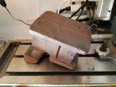
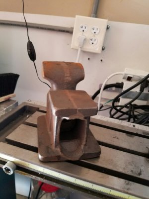
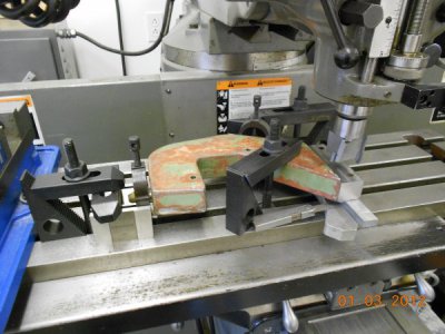
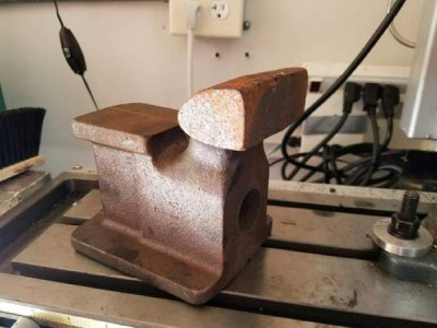
I have a vise casting. As a learning project I want to make the complete vise. Some of it is easy to figure out but, starting right off with a problem. Here is the casting. I want to make the bottom flat and as level as possible so I have a basis to machine the top and sides correctly. I have a small mill and lathe but, nothing like a surface grinder. I can't put in mill vise upside down because it is unsupported using the curved jaw or the jaw keeps me from clamping on the anvil part.
SO, how do I mount this part to machine the bottom flat?
vise2.jpe

vise1.jpe

vise3.jpe

I'd appreciate some tips/help.
Thanks,
Regis
 
Based on the pic.
I'd remove the vise from your mill.
If you have 123 or 246 blocks use those or substitute cold rolled (CR).
I've been using CR cut in pieces a little over 123 with a plan of making some unhardened 123 blocks--- someday.
Use hold downs and careful clamping to secure the vise to the mill table.
Be sure to Line up the base 90degrees to the where the threaded rod and vise jaw will be so that all will be square.
Keep in mind your tolerances. As any project can drive a person nuts trying to get it perfect.
If you need help with proper clamping techniques please ask.
If this thing takes flight it will leave a mark.

Also, consider that you may want it stressed relieved.
As it will "move less" as you take metal off.
But, there I go trying to get her all perfect again!!

Cool project!!

Daryl
MN
 
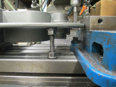
I'm in a little disagreement with Daryl on this one. I would put the jaw in the vice and let it hang out over the table. Then put a jack screw under the anvil and a clamp in the opening in the back. That will anchor both ends.

Here is how I supported an arbor press that needed some machining. The jack screw is a stud and a couple of nuts from my clamp set.

upload_2016-8-10_7-33-22.png

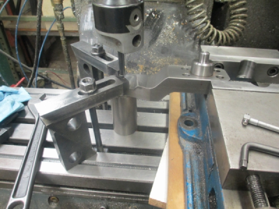
Here is another setup of an odd shaped part. In this case I used a chunk of cold rolled shafting for the outboard support. Just using the vice for support in this case, it's not bolted down, and is sitting on a couple of pieces of particleboard to raise the height.


upload_2016-8-10_7-36-32.png
 
That will do the trick for me. I have adequate blocks, clamps, and bolts for jack screw. And, Daryl, appreciate your reminder on being sure to level with the threaded rod/ lead screw.

Thanks all, now to work
Regis
 
Jim Dawson,
You trump me on this machining topic in every direction.
I was thinking about it in terms of a mill or lathe rebuild.
Usually you go back to the column or bed and work up or out.
Then flipping it to do align the screw and jaw to the base.
Using the vise to grip the jaw makes sense as long as I don't loose track of the order of operations and the priority of each step in the sequence.

Daryl
MN
 
Daryl, you were correct to mention aligning to the screw. I hadn't thought of that.

Sometimes figuring out how to hang on to something is half the job. In this case, there is no flat starting point so you just kinda have to pick a point. A rough casting is one of the most difficult things to find that point. You pretty much have to machine the whole project in your head before you can decide where to start. Order of operation becomes critical.:)
 
RegisG,
You will do well to listen to the wisdom of Jim and his ilk.
HM is a great site with little ego to impede learning and results.
Hang on, ask lots of questions, it'll be a wild ride!

Daryl
MN
 
Regis,
This is one of those projects that you'll probably spend more time trying to figure how to do than you will actually doing it. You just have to get a little creative when you're dealing with odd shaped pieces. You've gotten some good advice here and as stated above, the alignment of the bore with the base will be critical. It appears that the bore is still in as-cast form, but you may be able to put a temporary arbor through that hole and lay it in v-blocks to get a decent alignment to begin work. I did something similar a few years ago when machining a follow rest casting. I will attach a photo, and you may be able to see where I used round bar stock in the two existing holes for the fingers and clamped them in v-blocks. Also, I just noticed that I also used some feeler gauges to get the level dialed in. Hope this helps a little.
Ted
DSCN0297.JPG
 
It may sound a bit funky, but I'd check the general thickness of the bottom corners and check the top flat to see how close they are for a start (quality of the casting). If they're pretty close, I'd use a 4" angle grinder to carefully smooth the top flat - frequently checking it with a straight edge in all directions. Then I'd mount it on the top flat in the mill and hit the bottom. I would then turn it back over and mount it on the bottom and finish the top flat in the mill. Now I have two perfectly flat parallel surfaces to work on for the remainder on the project. It would save a lot of time creating elaborate set ups. It's not like it's a rare engine block or something. Keep your perspective of what it is your working on; it's just a vice.
 
A +1 on what Fabrickator said. For the first step, I might even just mount it bottom down on the mill table. Straddle that casting seam over a “T” slot. Maybe do a little shimming if needed. And then machine the top side flat. Flip over and do the bottom. NOTE: keep an eye on web uniformity. Don’t think the feed screw hole for level is going to be that critical. Maybe just alignment unto itself. It’s just a vise…Dave.
 
Back
Top