Motor wiring mystery

Makintrax73

H-M Supporter - Silver Member
Joined
Jun 20, 2022
Messages
206
I just purchased a round column mill rf25 or similar. It was RUNNING under 110v when purchased. Seller says it works fine. I saw it run.

Here's the problem....it appears to be actually wired for 220v. And it appears someone MAY have added aftermarket capacitors to the system.

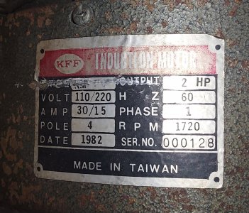
Here is the motor information:

20230504_054809.jpg

20230504_053707.jpg

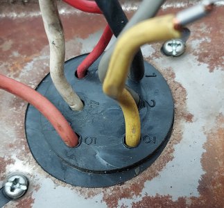
Here is what it looks like under the junction box

20230502_133723.jpg

Here is the wiring diagram as it was wired when disassembled for transport.

20230504_055740.jpg

Further to follow
 

Attachments

  • 20230504_053707.jpg
    20230504_053707.jpg
    530.7 KB · Views: 2
Last edited:
OK so my questions:

1) Clearly this is not wired correctly right? EXCEPT FOR THE CAPACITORS it is wired exactly as it would be for 220v. THE 110v PLUG IS SPLICED ONTO THE POWER CORD.

2) Do you think this motor was struggling because it was not getting enough voltage and someone added the caps later? They don't appear in the wiring diagram anywhere. The caps are IN THE JUNCTION BOX not on the outside of the motor as you normally see. But if the guy who did it knows how to wire in caps why didn't he re-wire it correctly for 110v.

3) What should I do from here?

My gut says pull the caps out of the system and wire the motor exactly as it is shown on the diagram under the junction box without the caps?

I AM ABSOLUTELY AWARE 2HP ON 110V IS NOT RECOMMENDED. I do not have any open spaces in my breaker panel. An additional 220v plug in my shop is a last resort. If I can make this work safely on 110v without burning it up that's what I need to do. I really would simply like to get this up and running and try some cuts and drilling to make sure the rest of the mill actually is solid before I pour a bunch of more money into wiring.

@markba633csi - you were extremely helpful and knowledgeable with wiring up a drum reversing switch. This is a very time consuming problem, if you feel you have the knowledge base to give me some insights I would be willing to send a couple dollars to you for your time?
 
OK let's review- first of all, this type of motor always requires at least one start capacitor to run properly. It won't start properly without any. The factory diagram is incomplete as it doesn't show the caps at all.
Second, while 230 volts is preferable, we can wire it for 115 first if you want. Currently it is wired for 230 volts
It looks like the wires originally had numbers but they are gone. It would be best to "ring out" the wires with an ohmmeter. Do you have one?
We need to double check the colors with the numbers- I don't trust anything a previous owner did.
Also, can you read the values on the two caps?
-M
 
Last edited:
OK let's review- first of all, this type of motor always requires at least one start capacitor to run properly. It won't start properly without any.
Second, while 230 volts is preferable, we can wire it for 115 first if you want. Currently it isn't wired correctly for either voltage.
It looks like the wires originally had numbers but they are gone. It would be best to "ring out" the windings with an ohmmeter. Do you have one?
We need to double check the colors with the numbers- I don't trust anything a previous owner did.
Also, can you read the values on the two caps? Tell me what they are.
-M

There are numbers on the gromet coming out of the windings so I'm confident my hand drawn diagram showing current wiring is accurate.

I do have a reasonably good MM when I get home in a bit I can try the caps.

Thank you!
 
OK this should be easier then. I'll post a quick sketch on what to change.
Tell me what is printed on the caps- you don't need to try and measure them.
This should work: add the second cap if necessary if it has trouble starting with just one
Swap 5 and 6 if necessary to reverse motor rotation
Maxwiring1.jpeg
 
Last edited:
Here is a better picture of the motor taps:

20230504_102328.jpg

Here are the caps:

20230504_103924.jpg

Me trying to test the caps it flashes over to this:

20230504_103512.jpg
 

Attachments

  • 20230504_102328.jpg
    20230504_102328.jpg
    377.1 KB · Views: 1
If I ohm test them one shows about 15M ohms.


The other one shows 0F
 
You don't need to measure the caps- let's assume they are both good.
You will probably want to use them both in parallel
 
I'll bench test it later today and report back

THANKS. Please let me know what I can do to pay you something for your time.
 
Your meter has a capacitance function- you should be able to read microfarads directly- maybe it won't read values that high? What model is that?
You need to discharge the caps before trying measure them- a damaged meter can result if you don't- as well as a nasty shock
You should be reading something around 300 uF

So your motor does not use a run cap. Only two start caps in parallel which is the same as one big cap.
My fee is one billion likes, payable in installments :)
PS Your meter is a 22-801 isn't it? I looked it up it only reads to 40 uF. Not much help with caps this big
Try the caps anyhow and see how the motor works
 
Last edited:
Back
Top