Monarch 612-2516 lathe

Different model and it's been 3 years so...
I was unable to pull the saddle on my 12CK without first pulling the apron.
I wanted to go through the metering valves and insure they were all oiling properly but wasn't willing to go through the work and inevitable mission creep to do it. Some day I will but for now I keep an oil can handy and use it regularly.
I pulled the carriage on my 12CK some years back, but I may continue the oil can route on this one for now. Doesn't look like there's a good way to do it without removing the apron first, which means removing the leadscrew and various shafts, which means opening up the QCGB. Yeah, mission creep.
 
Well, mission creep it is. After re-assembling the lathe, the cross-slide still has fairly significant a periodic roughness when turning the leadscrew. I now believe that is in the apron drive mechanism, so the apron will have to come off. To add insult to injury, last night the air compressor started sounding funny. Went outside to the attached shed that it lives in to a smell of burning rubber. Hoping it is just a loose drive belt, but it was getting late and wasn't going to start on that after dark.
 
Ok, guess I'll resurrect this 18 month old thread rather than random posts in What did you do/buy today? threads. I've jumped back onto this project now that I have a working overhead crane. I said working, not "completely finished". After all, this is a hobby, not a career.

The compound has been partially scraped, and internals cleaned up significantly, including removing the grease from the oil passages. There is a clear placard by the grease fittings that says something along the lines of Use Sunoco 80 Way oil, never the less, the zerks had obviously seen much and varying types of grease. WD-40, with the small straw, actually works pretty good for dissolving and blowing out old grease from those drilled passages. Assembly/casting that is on the right held an electromagnetic clutch for a tracer assembly associated with the cross slide. As mentioned in the "today" threads, I've removed the clutch assembly. New bearings on the left to hold the back end of the leadscrew in that casting.

Interestingly this cross-slide leadscrew is 0.4" per rev (2.5 TPI). My other Monarch is 0.5" per rev, so I've gotten use to two turns per inch. Hopefully since this is less it won't cause a real problem.
View attachment 486101
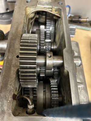
New for this post, I've also found the old oil pump that sat in the bottom of that casting. The pump was driven by the drive motor associated with the clutch and cross-slide leadscrew. With the motor gone and the clutch gone, nothing to operate the pump plunger, but I'm considering a handle or crankshaft to do that in lieu of buying a one-shot oiler and mounting it there. I believe that pump was responsible for oiling the carriage, but am not sure. There is also a pump in the apron, so I don't know for sure which pump handles what.

The carriage oil distribution system is mostly routed on the underside of the carriage. If you open this picture and look really close at the slot in the midde of where the cross-slide sits you can see a few oil lines going in/out of a manifold. I'm going to have to pull he carriage to really get at it and clean that up, and make sure it is working. Up to now I've been manually applying oil to the ways on the few times I've used this lathe. With the crunchy bearings, old grease, and the clutch system sort of attached, it made for a workout operating the cross slide. At least the carriage has power rapids. The compound before clean up was not really useable for cutting.

Anyway, going to have to pull the carriage off. I'm pondering possible ways to support the apron without the carriage so that I don't have to remove the bed leadscrew and various shafts, although I may need to do that anyway as the carriage clamps under the bed may not be feasible to remove with the apron in place.

View attachment 486102

Optimistically, I went ahead and ordered a new DRO from DRO Pros for this lathe. Getting a 2-axis EL-400, same as my other lathe. Another pricey purchase but I'm getting old enough I like the idea of identical buttons/layout/functionality across the two lathes' DROs. I had actually purchased a TouchDRO adapter, but I just can't get behind the idea of that many features. I'm a bit biased to KISS, and my older eyes don't like reading dynamic menus, leaning in across a spinning workpiece to squint at small fonts triggers my safety paranoia. Thinking I'll save the TouchDRO and use it on a mill project in the works. Extra features on a mill seems more practical there, for me. Just my opinions and reasoning, not trying to change anyone else's mind.
Any time I see a Monarch being cared for with loving and knowing hands brings a smile to my day.

Well done sir.
 
Well, mission creep it is. After re-assembling the lathe, the cross-slide still has fairly significant a periodic roughness when turning the leadscrew. I now believe that is in the apron drive mechanism, so the apron will have to come off. To add insult to injury, last night the air compressor started sounding funny. Went outside to the attached shed that it lives in to a smell of burning rubber. Hoping it is just a loose drive belt, but it was getting late and wasn't going to start on that after dark.
Taking the apron off is a great opportunity for us to see how they built them.
Lots of pics please.
 
Per @Janderso ’s request, a few pictures for today’s progress
First I pulled the compound and qctp off. About 146 lbs.
5727515D-33A7-4A43-8915-12200ADB02C6.jpeg

Then had to get all 4 apron shafts out, top to bottom: leadscrew, feed, rapids, and clutch.
74CA44E7-78EC-483C-BCC7-9590D64725A5.jpeg
The clutch and feed were held into collars on the qcgb via tapered pins. A bit painful to remove since the small side was down and toward the bed on the clutch which only rotates through around 90 degrees. Fortunately I hadn’t set the pins hard a few years back. The rapids had roll pins, a bit harder to deal with. Not sure if those were factory or may have originally been taper pins. The leadscrew toook a bit of work to get the bearing nut off the qcgb end. Ended up taking the cover off the qcgb, sliding the leadscrew back in place to give support to the leadscrew while removing the fine thread (32tpi?) nut. There is a setscrew through the nut sits against the threads so a spot on the threads gets distorted and the nut doesn't spin off easily.
4A92B294-BC18-49B5-95F6-78E21EF7D241.jpeg


Once all those shafts were slid out the right side of the apron it was time to drop the apron. Since the apron weighs 275 lbs that meant using the overhead crane
B07CB116-DAA1-463F-89B4-FC46A31EAA2C.jpeg

Carried over to the bench for inspection.

EAE346B4-2EB2-401F-A401-A67564B4EAFD.jpeg
The gear sticking out on the picture right (top of apron) is what engages the cross slide leadscrew. Here’s a close-up. If you look closely one of the teeth has a small amount of damage on the upper half, but that damaged didn’t extend into the tooth face. I did find one significant chip lodged between two teeth that was likely the culprit causing problems. While removing the apron I had noted that loosening the apron slightly was enough to resolve most of the issue.
43EA5CE7-60AD-456F-AB5E-344A787D7CC3.jpeg
This gear was a bit loose on the stationary shaft, not terrible but a little more than I would like if it was mount via a roller bearing.

The front of the apron is an aluminum plate on a cast iron body. To get that shaft out and check the bearing meant removing that plate. Which meant removing all of the control handles first.

E08FDED5-7ECF-4D9F-93E1-8D07F5BC950E.jpeg
The bevel gear on the bottom of the above picture engages the half-nut handle mechanism. That little gear was 80% of this project. It needed to come off to pull the faceplate. It had a roll pin through it that would not come out. After some work getting it out I realized what happened. The bevel gear was hand drilled to fit and had been drilled slightly off center. Someone had previously re_installed the beval gear 180 degrees off. Since the gear had been drilled slightly off center, the holes in the gear and underlying shaft didnt line up perfectly. A roll pin had been force fit through the offset holes and was well and truly jammed. Being very close to the faceplate surface, and more than a typical punch’s length from the edge of the faceplate added to complications. Persistence paid off eventually.
38E0415C-6905-41B6-941D-4E6DC4B4B884.jpeg
Fairly complex apron under there. Oil pump at top left of picture, Rapids mechanism along the left side. Lots of oil lines.
Did finally drive the shaft to the offending gear out. Turns out what I thought would be a bearing is actually a bronze bushing, and that while a bit loose is within what I would expect for bushing tolerance. I’ll probably turn another bushing and press it in since I got it all apart.

Before reassembling the apron I plan on cleaning it with a garden sprayer filled with diesel, and a catch bucket. It really does have some sludge in there and a few chips.

Didn’t get a picture of the apron rear, but the half-nut is something like 8” long. I’ll try to get a picture of that before rehanging it. But before rehanging the apron I’m also going to pull the carriage off and flip that over on the bench to clean and trace the carriage oil lines.
 

Attachments

  • 559BBDDD-46BD-4AD0-B510-C791E903C4FB.jpeg
    559BBDDD-46BD-4AD0-B510-C791E903C4FB.jpeg
    303.3 KB · Views: 15
  • A7536BC9-618D-4F88-8788-60FA02696EAD.jpeg
    A7536BC9-618D-4F88-8788-60FA02696EAD.jpeg
    434.3 KB · Views: 8
Last edited:
Thanks for the detailed write-up.
LTBC (love that bridge crane)
 
Degreasing/cleaning up. Gives a backside view of the apron. The spring loaded gear on the bottom right of the apron backside is torque limiter for the rapids, so it doesn't break something if run into the stops.
IMG_5410.JPG
IMG_5409.JPG
 
Per @Janderso ’s request, a few pictures for today’s progress
First I pulled the compound and qctp off. About 146 lbs.
View attachment 486477

Then had to get all 4 apron shafts out, top to bottom: leadscrew, feed, rapids, and clutch.
View attachment 486480
The clutch and feed were held into collars on the qcgb via tapered pins. A bit painful to remove since the small side was down and toward the bed on the clutch which only rotates through around 90 degrees. Fortunately I hadn’t set the pins hard a few years back. The rapids had roll pins, a bit harder to deal with. Not sure if those were factory or may have originally been taper pins. The leadscrew toook a bit of work to get the bearing nut off the qcgb end. Ended up taking the cover off the qcgb, sliding the leadscrew back in place to give support to the leadscrew while removing the fine thread (32tpi?) nut. There is a setscrew through the nut sits against the threads so a spot on the threads gets distorted and the nut doesn't spin off easily.
View attachment 486479


Once all those shafts were slid out the right side of the apron it was time to drop the apron. Since the apron weighs 275 lbs that meant using the overhead crane
View attachment 486476

Carried over to the bench for inspection.

View attachment 486474
The gear sticking out on the picture right (top of apron) is what engages the cross slide leadscrew. Here’s a close-up. If you look closely one of the teeth has a small amount of damage on the upper half, but that damaged didn’t extend into the tooth face. I did find one significant chip lodged between two teeth that was likely the culprit causing problems. While removing the apron I had noted that loosening the apron slightly was enough to resolve most of the issue.
View attachment 486475
This gear was a bit loose on the stationary shaft, not terrible but a little more than I would like if it was mount via a roller bearing.

The front of the apron is an aluminum plate on a cast iron body. To get that shaft out and check the bearing meant removing that plate. Which meant removing all of the control handles first.

View attachment 486473
The bevel gear on the bottom of the above picture engages the half-nut handle mechanism. That little gear was 80% of this project. It needed to come off to pull the faceplate. It had a roll pin through it that would not come out. After some work getting it out I realized what happened. The bevel gear was hand drilled to fit and had been drilled slightly off center. Someone had previously re_installed the beval gear 180 degrees off. Since the gear had been drilled slightly off center, the holes in the gear and underlying shaft didnt line up perfectly. A roll pin had been force fit through the offset holes and was well and truly jammed. Being very close to the faceplate surface, and more than a typical punch’s length from the edge of the faceplate added to complications. Persistence paid off eventually.
View attachment 486472
Fairly complex apron under there. Oil pump at top left of picture, Rapids mechanism along the left side. Lots of oil lines.
Did finally drive the shaft to the offending gear out. Turns out what I thought would be a bearing is actually a bronze bushing, and that while a bit loose is within what I would expect for bushing tolerance. I’ll probably turn another bushing and press it in since I got it all apart.

Before reassembling the apron I plan on cleaning it with a garden sprayer filled with diesel, and a catch bucket. It really does have some sludge in there and a few chips.

Didn’t get a picture of the apron rear, but the half-nut is something like 8” long. I’ll try to get a picture of that before rehanging it. But before rehanging the apron I’m also going to pull the carriage off and flip that over on the bench to clean and trace the carriage oil lines.
That apron is built to last and last and last......
 
Last edited:
That apron is built to last and last and last......
My one concern is the oil distribution system. Those metering valves on the manifold are known to plug up. If you look a couple posts back at the front of the apron with the faceplate removed, you can see what looks like grease but is actually sludge coming out of the shaft just below the oil pump (below based on the picture orientation). I think I'm going to pull each of the metering units off and see if I can gently stream WD-40 through them backwards. Mission creep but I don't want to have to break this down again in the near future.

Unfortunately the faceplate needs to be back on the apron for oil pump to have a reservoir, so it is challenging to test the system. I repainted the faceplate today but the Sherwin Williams enamel will take several days to dry enough to be handled so I have some time to work on that.

Another somewhat interesting feature of this apron, if you look at the bottom of the backside there is a phenolic (brown) rub pad complete with oil grooves that rides against the bed.
 
Got the metering valves all cleaned in the apron. Next step:

Carriage off. Scale in this picture shows the weight in pounds.
IMG_5415.JPG

Swapped it over to the forks on the loader to take it outside for cleaning the underside
IMG_5416.JPG

Serious cleaning required.
IMG_5418.JPG

IMG_5419.JPG
 
Last edited:
Back
Top