MK2 Metric Thread dial gears.

o0norton0o

Registered
Registered
Joined
Dec 3, 2023
Messages
81
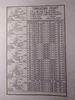
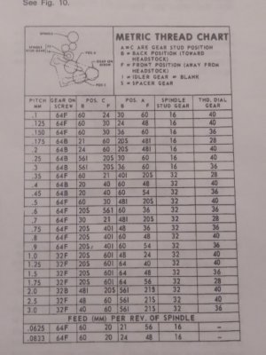
I've been trying to improve my skill set, so I have been reading a lot, watching videos and experimenting daily with my lathe because I want the parts I make to be excellent quality. I recently found that my thread dial actually has 3 different thread dial gear possibilities that are changed for threading different pitches. The only gear I have for my thread dial is the 28 tooth gear that is currently on there. The other 2 gear sizes according to my manual are 36 teeth, and 40 teeth. My threading chart shows which dial gear corresponds with which common metric thread pitches, so if I had them I could swap them when appropriate and not make mistakes based on trusting a thread dial with the wrong gear installed. :(

I called clausing and those gears are discontinued items, so my chances of buying the stock ones made for the machine is remote. I think another opportunity might be to buy a printed gear. I have a friend who does CAD for Microsoft, so I bet I can get him to print me a few gears.... I have to call him... I don't think they need to be made of metal because they are just turning a tiny dial. Finally, I'll make them myself out of delrin if I can't buy them.

Anyone have all their gears for their MK2 thread dial? Anyone make them or have them printed??

Thanks in advance for any help
 
You don't say if you have a metric lead screw, if you do not, the gears are unnecessary, as you need to keep the half nuts engaged all the time when cutting metric threads with an inch pitch lead screw with transposing gears.
 
I have already learned that fact the hard way, but in reverse, cutting imperial threads on my metric lathe....

My lathe is a true metric lathe with a 2mm lead screw. I was looking at the info plate on the lathe with the various metric thread pitches and their associated gear combinations and realized that my thread dial uses 2 other gears for some of those common metric threads. I wanted to have those other dial gears too, for when I cut the threads that need the other dial gears..... so here I am asking if anyone with an MK2 has all 3 dial gears for their lathe (either metric or imperial) just to see if they were commonly purchased back in the day....

and then I realized that I might have to make them..... or have them printed and wondered if anyone had done either of those. I've found a few people who have made their own complete thread dials on youtube. All I need to make is the 2 gears, which I am sure I can make, but it will take some time to make the jigs to hold the blanks to cut the teeth.... so I'd love to just buy them or find someone who prints these things and buy them already made.
 
Is your thread dial different from the usual single shaft unit? I'm not familiar with the metric version of the MK2
 
I have already learned that fact the hard way, but in reverse, cutting imperial threads on my metric lathe....

My lathe is a true metric lathe with a 2mm lead screw. I was looking at the info plate on the lathe with the various metric thread pitches and their associated gear combinations and realized that my thread dial uses 2 other gears for some of those common metric threads. I wanted to have those other dial gears too, for when I cut the threads that need the other dial gears..... so here I am asking if anyone with an MK2 has all 3 dial gears for their lathe (either metric or imperial) just to see if they were commonly purchased back in the day....

and then I realized that I might have to make them..... or have them printed and wondered if anyone had done either of those. I've found a few people who have made their own complete thread dials on youtube. All I need to make is the 2 gears, which I am sure I can make, but it will take some time to make the jigs to hold the blanks to cut the teeth.... so I'd love to just buy them or find someone who prints these things and buy them already made.
If you published some specs on the gears you need, perhaps someone on HM might print them for you. Need the bore, thickness, module and number of teeth and any other special features. The gear design itself is pretty easy for anyone that has CAD. If you don't know the module, then provide the OD of the gear, the module can be estimated by the number of teeth and the diameter.
 
Is your thread dial different from the usual single shaft unit? I'm not familiar with the metric version of the MK2
As usual, I start out knowing Zero! and as I research, I find out a lot. Unfortunately for people who are learning, you don't have enough experience to know if there are things you're missing. I've seen thread dials with multiple stacked gears, that I suppose the person rearranges the stack to suit the pitch they are cutting so their dial always works. I've seen dials with asymetrical marks that I assume always use only a single mark but each specific dial mark is assigned to a certain pitch/es.

My thread dial is a single shaft with a single gear and 4 evenly spaced marks on the dial. I assume you knock the current gear off and replace it with the corresponding correct gear for the pitch you are cutting. I doubt very much my metric thread dial is any different than the imperial thread dial with the exception of my manual shows 3 gears for it. My metric threading chart has a column that shows which pinion goes on the thread dial for each pitch you chose to cut. I also have to MK2 Imperial manual and it does NOT have any extra pinions for the thread dial, nor does it have a column that shows thread dial pinion options....

...so that answers the question why you don't know why I'm asking about multiple thread dial gears. It must be something that metric lathes require, but imperial lathes don't need...
If you published some specs on the gears you need, perhaps someone on HM might print them for you. Need the bore, thickness, module and number of teeth and any other special features. The gear design itself is pretty easy for anyone that has CAD. If you don't know the module, then provide the OD of the gear, the module can be estimated by the number of teeth and the diameter.

This is the fun part. I feel like I can find the mathematical relationship between any gear size and number of gear teeth because I have a gear to measure to find that relationship, ... so

my existing 28 tooth thread dial pinion is 19mm diameter. So,...

then a 36 tooth gear is 24.428571428571428571428571428571mm diameter

and a 40 tooth gear is 27.142857142857142857142857142857mm diameter

I'm not up to speed on printing parts with a cad program. Something tells me that the guy who makes this won't get the angle of the pinion correct. Needless to say that diameter is simple and the tooth form is easily copied, but the thread angle of the pinion is had to be something the software already has written into it in order to produce a gear with that angle....

I'm going to text my friend this morning because I'm so curious now... He's a young microsoft engineer. When I first met him he was smelting aluminum in a home made furnace in his driveway,.... I thought,... "This guy is cool".Imperial MK2 thread chart1.jpgMetric MK2 thread chart1.jpg
 
Last edited:
According to my calculations, ( https://khkgears.net/new/gear_knowledge/abcs_of_gears-b/basic_gear_terminology_calculation.html ) the tip diameter d_a for a metric gear is:

d_a = zm + 2m = (z+2)*m, where z is the number of teeth, and m is the module

Given d_a = 19, we get 19 = (28+2)m. Solving for m gives us m = 19/30. That's not a common module. Can you measure that diameter again? I'd believe maybe 2/3, or 1/2, but 19/30 seems weird. If you don't get the module right, things will be nasty. You have to have the same (or really really close) modules to mesh.

Your dial assembly has to accommodate the vastly different diameters of the gears. The shaft locations HAVE to change, if you put in larger gears. Can you show a picture of this?

Most metric gears use 20 degree pressure angle.
 
The 19mm was a quick measurement, just to see if the approximate diameters of the other two gears would be reasonably sized to work. and I think they are... the largest one is just over 1 inch. it will fit fine because the swing of the dial body and the height of the pinion will accomodate the change in the body position ...

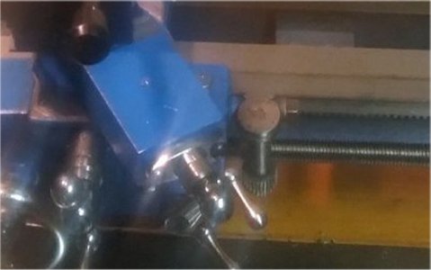
cool formulathreading dial1.jpg
 
Last edited:
A 28 tooth gear with an o.d. of 19 mm would have a modulus of .633. OTOH, 28 tooth gear with an o.d. of .748" (19 mm) would have a diametral pitch of 40.05. I suspect that the lathe has Imperial gears. If the lathe were offered with an option for a metric lead screw rather than a standard Imperial lead screw. I would suspect the latter is the case.

Regarding CAD generation of gears, they are not necessarily true to form. I know that is the true for my 2012 version of SolidWorks. There is a third party add on which will generate a geometrically accurate gear but it is somewhat cumbersome to use as it requires parametric equations .

From what I have seen, McMaster Carr's 3D gears are geometrically accurate and my approach is to download the model and modify it to meet my needs. Another way to create accurate gear models is to download them from SDP/SI's site and modify them to my need.
 
I got in touch with my engineer friend who does CAD design for Microsoft hard products. He has 3D printer at home, and while printing gears is not what he does for a living, he designs all the plastic parts for laptops.

I have 1 of the gears out of the 3 that are supposed to go with my thread dial. That gear is currently mounted on my thread dial and is a metal gear. I'm sure I can measure the helical angle, and use the math from the ratio of that gear's diameter/# of teeth to extrapolate the diameter of the other 2 gears. My theory is that if I can get the tooth geometry right, and the diameter ratio of each gear right, then the gear should work correctly. It is only turning a dial, so it's not anything with a load on it.

My plan is to see if he can 3D print the existing 28 tooth metal gear that I have in a nylon material. If it comes out exactly the same as the metal gear, then I think it should work for the other 2 gears which are 36 and 40 tooth.

Other than that solution, I still think I can make a jig to cut the teeth because I am a cabinet maker, and I have always made crazy stuff much harder than cutting a plastic gear... (but it would be awesome to just have it printed and save me the trouble of building an elaborate jig :D )

See any flaws in my logic? Thanks again for the comments and help....

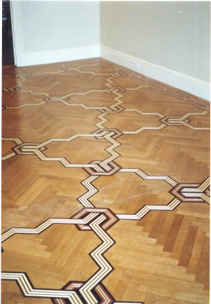
Here's a floor that I built a 26' long straight edge and router jig to inlay this pattern into an existing herring bone white oak floor on 5th ave in Manhattan NYC if anyone doubts my ability to measure accurately and build a jig...

zilka's floor.jpg
 
Back
Top