- Joined
- Oct 13, 2014
- Messages
- 6,852
I need a roll bender for an up coming project. The plan was to borrow the one I thought my friend and former business partner had, but sadly, he no longer has it. Last thing I need is another project, I didn't want to spend huge amount of time fabricating one. So I set out to cobble something together...
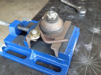
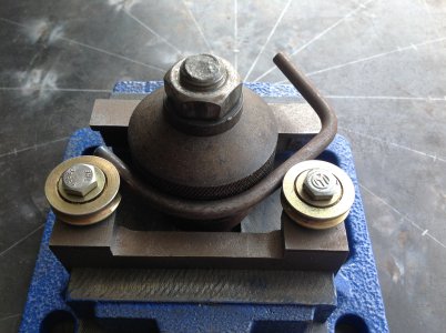
A little digging through one of the the scrap bins revealed the large knurled "drive"roller, it is 3" in diameter and bored through about 1.5" it also has a 2" diameter .375" high shoulder on the bottom. I made a bushing to fit inside the bore, tapped in the center for a ½" bolt and welded it in place I then thought to weld a sacrificial socket (I have many duplicates) to the top of the roller but I lucked out and found that a 1⅛" socket had a perfect friction fit, so I simply pressed it in place.
Next another scrap bin delivered 2 six inch-ish long, pieces of 3"x4" angle. I cut the short leg on one of them down about .375" and drilled both of the short legs to align with the bolt holes in the mill vise, that way one would ride over the other. I then drilled a hole in the long top leg of the angle with the shorter leg, to mount the drive roller, a brass bushing and a cap screw fastened in place and allows it to turn freely.
Finally I notched the top of the other angle to clear the shoulder of the drive roller and drilled and tapped the holes for the 2 back rollers. I made the rollers out of 1.5" diameter aluminum bar stock and fasten them with some scraps of threaded rod.
Once bolted on to the vise I completed the drivetrain with a couple of flex type socket extensions, this allows for some misalignment, sort of a makeshift universal joint. While the X axis of the drive roller is centered perfectly, the Y axis changes as I progressively move it towards the back rollers. I still need to move the Y axis of the mill to get it more or less centered to the mills spindle, but it isn't critical.
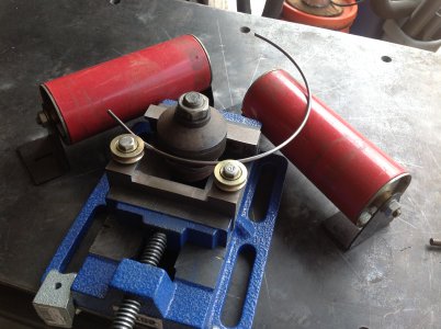
The results from my first attempt were better than I expected.


I then TIG welded the ends together and placed it back in the jig.


A little digging through one of the the scrap bins revealed the large knurled "drive"roller, it is 3" in diameter and bored through about 1.5" it also has a 2" diameter .375" high shoulder on the bottom. I made a bushing to fit inside the bore, tapped in the center for a ½" bolt and welded it in place I then thought to weld a sacrificial socket (I have many duplicates) to the top of the roller but I lucked out and found that a 1⅛" socket had a perfect friction fit, so I simply pressed it in place.
Next another scrap bin delivered 2 six inch-ish long, pieces of 3"x4" angle. I cut the short leg on one of them down about .375" and drilled both of the short legs to align with the bolt holes in the mill vise, that way one would ride over the other. I then drilled a hole in the long top leg of the angle with the shorter leg, to mount the drive roller, a brass bushing and a cap screw fastened in place and allows it to turn freely.
Finally I notched the top of the other angle to clear the shoulder of the drive roller and drilled and tapped the holes for the 2 back rollers. I made the rollers out of 1.5" diameter aluminum bar stock and fasten them with some scraps of threaded rod.
Once bolted on to the vise I completed the drivetrain with a couple of flex type socket extensions, this allows for some misalignment, sort of a makeshift universal joint. While the X axis of the drive roller is centered perfectly, the Y axis changes as I progressively move it towards the back rollers. I still need to move the Y axis of the mill to get it more or less centered to the mills spindle, but it isn't critical.
The results from my first attempt were better than I expected.
I then TIG welded the ends together and placed it back in the jig.