Mill Leaving Ridges While Face Milling

Cmesler

Registered
Registered
Joined
Feb 19, 2016
Messages
66
So I recently picked up a valenite 3" face mill and just getting around to trying it today. I stuck a piece of 4" aluminum in the vise, on the parallels and took a .200 pass. Feeding from left to right it left a semi mirror sort of ghostly finish. When I moved the y in and took the last 1" or so pass coming back across it was leaving a very noticeable ridge but was leaving a mirror finish. As it came close to the end of the cut it was about flush with were the first pass was.
I just trammed the mill after I used it the last time and over the span of half the bed 25" give or take, It's within .0007.
So can anyone enlighten me on to what is going on its starting to baffle me.
 
Run the operation a second time and if the same thing happens again, same error at the same position then the Y axis ways are uneven, this is all that it can be all other parameters being equal.

As a second test run both cuts in the same direction in X.
 
WP_20160426_17_54_01_Pro.jpg WP_20160426_17_54_39_Pro.jpg C:
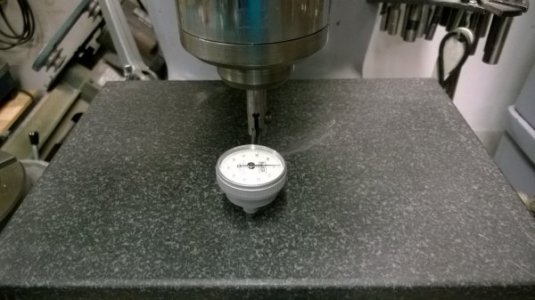
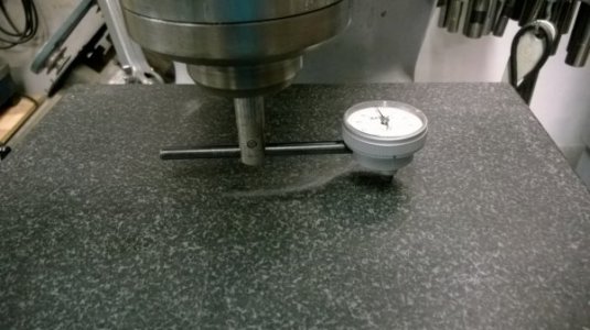
Moving the table one way or another does not tram the spindle in. If your mill has a "universal head" like a Bridgeport, no step will disappear unless your head is trammed in to your table. You don't move the table to put the face of your cutter parallel to X and Y. Put a dial indicator into your spindle with the tip parallel, a couple inches out from the spindle. Rotate the spindle by hand and see if there is any + or - movement and adjust accordingly. There are a couple of pictures below to show you what I use on my Bridgeport. in the pictures I placed a granite block on my vice just for illustration. Do your measurements directly on the table but don't move anything but the spindle.

Good Luck, Gary
 
Okay thanks for the advice guys I'll try that tomorow.
-Chris
 
Mills are always gonna leave a mark when doing that, They are just not precision machines.
Not a ridge but a visible mark that you can't feel with a fingernail is about as good as it gets.
When the end mill hits the work it will be pushed up when it leaves the work it will drop off.
For 4" block a 4 1/4 face mill would make a nice finish .... other wise the surface plate and some fine sandpaper
will flatten and even out the surface nicely. Lapping plate would be ideal so you could keep the abrasive away from the surface plate.
 
Blast it with Glass bead , marks are gone , clean , ready for powder or paint.
 
Proper tramming of the mill requires that the spindle axis be perpendicular to a plane parallel to the x and y axes. When tramming to the table surface, the assumption that the table surface is parallel to the x and y axes but this is not necessarily true. A way to test the table for paralleness is to mount an indicator in the spindle and sweep the table in both the x and y axes. I did this on my Tormach 770 and found that the table increased in elevation .0012" over 14" in the x direction and .0010"over 6" in the y direction.

To properly tram the head, I would first face a plate clamped to the table with a small diameter end mill. This will ensure that the faced surface is truly parallel to the x and y axes. You want to use a small diameter end mill as an out of tram head will not create a s high a ridge. If the head misalignment is .005" in 5", the ridge height would only be .0005" for a half inch end mill. Use that surface as the tramming surface.
 
Tramming your mill is the first thing to do. That may not correct the "ridge" situation entirely. When taking a .200" depth of cut with a 3" face mill you are going to get some deflection in your machine. This deflection will show up in the surface of your machined part, aka "ridge". After taking your .200" deep pass follow with a .010" to .015" deep pass. If your mill is properly trammed and you take a light finish pass the cutter overlap will be almost unnoticeable.

Tom S.
 
Thanks RJ, I'm thinking a new disk brake rotor 10" "trued up" to tram with , any thoughts ?.
 
Thanks RJ, I'm thinking a new disk brake rotor 10" "trued up" to tram with , any thoughts ?.
I plan on just facing a 6" x 6" area on a piece of aluminum plate. I would expect to have to reface or at least check the face every time I wanted to check the tram.

I haven't done my Tormach yet. It is a bit involved as the spindle has to be parallel to the z axis ways first. I checked alignment that using "Rollie's Dad's method and corrected to .0005" in 6" in x and .0009" in 6" in the y direction. I would like to get it a bit closer in the y direction but that will involve shimming the head. Once I am satisfied with the spindle alignment, the actual tramming will involve shimming the base of the z axis column. Before undertaking that , I want to check the level of the mill to ensure that I am not twisting the base. I am getting closer, having made a tramming indicator (the Traminator ;)) and bought a shim pack. I still need to acquire a precision level.
 
Back
Top