-
Welcome back Guest! Did you know you can mentor other members here at H-M? If not, please check out our Relaunch of Hobby Machinist Mentoring Program!
You are using an out of date browser. It may not display this or other websites correctly.
You should upgrade or use an alternative browser.
You should upgrade or use an alternative browser.
Mike's 6-Axis Articulated Robot
- Thread starter macardoso
- Start date
- Joined
- Mar 26, 2018
- Messages
- 2,724
Well after a year I guess it is time to throw a few updates here! Starting with last year's Halloween display, here are a couple videos of the robot running - it was a complete hit.
Overall it worked very well. There were a few understandable hiccups with the gripping of randomly shaped plastic bags. The real issue was the bags getting stuck in the drop chute. I am modifying the display this year to change how the drop chute is set up.
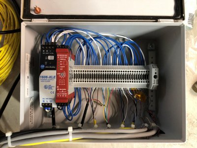
I've also rewired the junction box for field devices to be much more compact and tidy. I tore the old one apart last year and didn't leave myself any notes about how it was set up. Took a good couple hours to reverse engineer the wiring I had previously. This box is small enough to keep wired up for next year's display. The cables come through the lid, but I can easily add cord grips if needed.
I'll be running the display again tomorrow so new videos coming.
Started having conversations with a guy from Germany who also has this same robot. The only other one I've heard of. We've been sharing information and trying to get his unit up and running. He was able to share a couple manuals that I didn't have which is great. He wants to use his for 3D printing and stream data to it over serial. this got me thinking about how to accomplish the interface and it seems possible.
I've also started playing around with some of the fancier features of the robot including the "Easy Multitasking" mode. Normally the robot can only execute one command at a time (move, output on, logical expression, set value, etc.) so when the robot is moving, it can do nothing else. The E_MUL command (multitasking) allows the controller to start a limited subset of the instruction set asynchronously and execute while moving. You can do a lot of things with this like turning on outputs, running timers, or (usefully to the serial streaming application) send/receive position data over serial. The major limitation I've hit is that you cannot save a new value to a variable (S I0001 = 10) during multitasking, so setting up for loops or copying data while the robot is moving seems impossible. Denso must have been aware of this limitation because there is one special accessible register for position data received over serial that can be written to and read from during multitasking (VDT). This would have typically been used for getting vision data. If you try to run a command which is not supported during multitasking, the robot simply waits for motion to complete before executing that command. At the end of multitasking, you can issue an E_MULEND command.
Looking into developing a simple Windows application which can load position data from a text file and stream the commands to the robot. I could even use a CAM package to write a toolpath, then strip out all the G and M codes, leaving only the position data.
Mike
Overall it worked very well. There were a few understandable hiccups with the gripping of randomly shaped plastic bags. The real issue was the bags getting stuck in the drop chute. I am modifying the display this year to change how the drop chute is set up.
I've also rewired the junction box for field devices to be much more compact and tidy. I tore the old one apart last year and didn't leave myself any notes about how it was set up. Took a good couple hours to reverse engineer the wiring I had previously. This box is small enough to keep wired up for next year's display. The cables come through the lid, but I can easily add cord grips if needed.
I'll be running the display again tomorrow so new videos coming.

Started having conversations with a guy from Germany who also has this same robot. The only other one I've heard of. We've been sharing information and trying to get his unit up and running. He was able to share a couple manuals that I didn't have which is great. He wants to use his for 3D printing and stream data to it over serial. this got me thinking about how to accomplish the interface and it seems possible.
I've also started playing around with some of the fancier features of the robot including the "Easy Multitasking" mode. Normally the robot can only execute one command at a time (move, output on, logical expression, set value, etc.) so when the robot is moving, it can do nothing else. The E_MUL command (multitasking) allows the controller to start a limited subset of the instruction set asynchronously and execute while moving. You can do a lot of things with this like turning on outputs, running timers, or (usefully to the serial streaming application) send/receive position data over serial. The major limitation I've hit is that you cannot save a new value to a variable (S I0001 = 10) during multitasking, so setting up for loops or copying data while the robot is moving seems impossible. Denso must have been aware of this limitation because there is one special accessible register for position data received over serial that can be written to and read from during multitasking (VDT). This would have typically been used for getting vision data. If you try to run a command which is not supported during multitasking, the robot simply waits for motion to complete before executing that command. At the end of multitasking, you can issue an E_MULEND command.
Looking into developing a simple Windows application which can load position data from a text file and stream the commands to the robot. I could even use a CAM package to write a toolpath, then strip out all the G and M codes, leaving only the position data.
Mike
Hi, I'm David
Have you ever experienced "Error 106" when starting up the robot arm and at the end of the steps to calibrate the motors of each axis ?
I checked the error codes table and still can't resolve this error...
My arm is the same model as yours. It is also a second-hand robotic arm that has been idle in the warehouse for more than 6 or 7 years.
There are exactly two sets of robotic arms and controllers (but after checking the RANG value on the sticker, I determined these four, they are not in the same group as each other...), it was confirmed that both sets of robotic arms could work normally before being idle.
I calibrated the motors of each axis according to the service manual and other files you shared with you in the project record on this web page.
However, I encountered many problems during the calibration.
The project status recorded on your web page was also something different.
My steps are as follows :
I first replaced the two types of batteries, turned on the power, and executed "Memory Clear Mode".
Then "Error 106" was displayed every time I turned on the power (but it could be cleared by pressing the C button), and then when using the shorting jumper to perform an encoder reset , only J1 and J2 will display Error 771 and 772 after reset, but other axes do not display any errors.
Then when doing the CALSET operation of each axis, J1 and J3 can be completed successfully and display "CAL OK", but J2, J4, J5 and J6 will not display "CAL OK" at the end of calibration, but will display "Error 106".
I would like to ask if you have encountered the above problems during the calibration process ?
If not, what do you think might be causing this problem ?
I am Taiwanese and my English is not good enough, so I use a translator, sorry about that.
Thank you very much for spending a lot of time reading this message.
I hope you can reply to me when you have time, thank you.
Finally, thank you very much for your project record, it really helped me repair this robotic arm!
I wish you all the best
David
- Joined
- Mar 26, 2018
- Messages
- 2,724
Hi David,Hi, I'm David
Have you ever experienced "Error 106" when starting up the robot arm and at the end of the steps to calibrate the motors of each axis ?
I checked the error codes table and still can't resolve this error...
My arm is the same model as yours. It is also a second-hand robotic arm that has been idle in the warehouse for more than 6 or 7 years.
There are exactly two sets of robotic arms and controllers (but after checking the RANG value on the sticker, I determined these four, they are not in the same group as each other...), it was confirmed that both sets of robotic arms could work normally before being idle.
I calibrated the motors of each axis according to the service manual and other files you shared with you in the project record on this web page.
However, I encountered many problems during the calibration.
The project status recorded on your web page was also something different.
My steps are as follows :
I first replaced the two types of batteries, turned on the power, and executed "Memory Clear Mode".
Then "Error 106" was displayed every time I turned on the power (but it could be cleared by pressing the C button), and then when using the shorting jumper to perform an encoder reset , only J1 and J2 will display Error 771 and 772 after reset, but other axes do not display any errors.
Then when doing the CALSET operation of each axis, J1 and J3 can be completed successfully and display "CAL OK", but J2, J4, J5 and J6 will not display "CAL OK" at the end of calibration, but will display "Error 106".
I would like to ask if you have encountered the above problems during the calibration process ?
If not, what do you think might be causing this problem ?
I am Taiwanese and my English is not good enough, so I use a translator, sorry about that.
Thank you very much for spending a lot of time reading this message.
I hope you can reply to me when you have time, thank you.
Finally, thank you very much for your project record, it really helped me repair this robotic arm!
I wish you all the best
David
Welcome to Hobby Machinist!
Do you have access to all the manuals for this robot? If not, I can find a way to share them with you.
From my understanding, Error 106 is a result of the lithium primary battery in the controller going dead. You can reset the RANG values all you want, but if you don't replace the battery then it will continue to lose memory. I do see you stated you replaced the controller battery, but worth a double check of both polarity and voltage.
If you have not done so, double and triple check all the connections in the robot body per the maintenance manual.
Can you tell me the full part number of the RC3 controller (such as RC3-V6A)? There are dozens of robots supported by the RC3 controller family, but the controllers are different configurations for each one. You would need the RC3-V6A controller to run a VS-6354 robot.
The memory clear procedure provided to me by Denso is as follows. I did not need to perform this, as my controller battery never died.
1) RC3 All clear command to wipe out memory area:
Press [BCLR] [1409] then [Enter]. Then Press [Sure] then [Rec] keys.
2) Clear all programs and variables:
Press [BCLR] [123] then [Enter]. Then Press [Sure] then [Rec] keys.
From there, you should be able to power cycle the controller without getting an Error 103 or Error 106 when first powering on the RC3 controller. (Owners Manual A, page 6-15 thru 6-18)
At this time I would also double check the robot encoder backup battery voltage and polarity. You can verify this at the motor connector inside each joint of the robot. Make sure all 6 motors are getting 3V. (Owners Manual A, page 6-13 thru 6-14)
Now perform the encoder reset procedure (Owners Manual A, page 6-23 thru 6-29).
I found if you have not configured PLIM, NLIM, and RANG, then CALSET may fail. Start the Limit Definition Procedure (Owners Manual A, page 5-82 thru 5-87). Note that after you finish entering the PLIM and NLIM values per the manual the RANG1-RANG6 values are the next to show up. The manual does not tell you how to enter or modify these, but this is the time to enter those values from the sticker on the base of your robot.
If this works it is time to CALSET the robot (Owners Manual A, page 5-88 thru 5-95). I did not have the J6 Calibration jig, so I had to develop my own method of calibrating J6 by measuring the angle of a flat I milled onto some end of arm tooling relative to a flat plane. It isn't perfect, but it works!
If you have gone through these steps and are still getting stuck, please record you exact steps (keypresses, actions, etc.) and the resulting error codes displayed on the pendant. I'll dig in deeper to see if I can help.
I'd love to see photos of your setup if you are willing to share. Do you have any of the accessories like the operation panel, floppy loader, vision system, etc.?
Good luck,
Mike
I can access it. I have the Owner's Manual A, B, and Service Manual that you shared on the Robot-Forum page.
There should be no other manuals, right?
Yes I have replaced the controller battery and checked the polarity and voltage, I will check again to make sure that part is ok.
My bad, I forgot to explain my setup first, my setup is as follows:
1. Robot Arm: VS-6354C (V9.58)*2
2. Controller: RC3-V6A (with Operation Panel)*2
3. Teaching Pendant (410100-0560)*1 (The original 410100-0110 and -0120 cannot be purchased on ebay, so I bought one that looks the same and has six axes controll batton. Everything is working fine now)
4. Cable: Power Cable *2, Motor Cable *2, Encoder Cable *2
5. Other: Suction cup installed on J6*2, fiber amplifier used with the suction cup (Keyence FS-N11N, originally seems to be used to sense the distance of the workpiece)*2
Apart from the above, I have no other accessories, cables, connectors, floppy disks and the like.
I changed the battery because after turning on the power for the first time, many errors popped up.
According to the error code instructions, I directly replaced the batteries of the controller and arm (the same specifications and voltage as the original ones).
I Forgot to measure the original battery voltage first.
But turning the power on again did eliminate those error codes.
It turns out that my memory clearing program only did the [BCLR] [123] part, and I didn’t see the [1409] part required in the Owner’s Manual.
This may also be the cause of Error 106.
After Error 106 started to appear, I also measured the voltage of the controller battery and each Robot Encoder Backup Battery again, but I have not yet carefully measured whether the motor connector of each joint of the robot has the correct voltage.
I will measure again to ensure this part is normal.
It is true that I have not reconfigured PLIM, NLIM, and RANG.
This may also be the reason why I cannot calibrate successfully.
I only suspected this when I re-read the Owner's Manual a few days ago.
According to your explanation, the probability is very high.
I may be able to calibrate the J6 using the suction cup base mounted on it, it should be feasible
OK, thank you for your reply and detailed step-by-step instructions.
This really helps me a lot, otherwise it might take me several months to figure out what the problem is
Certainly! I'd love to share photos of my setup!
This is a photo taken last month when the calibrate started:
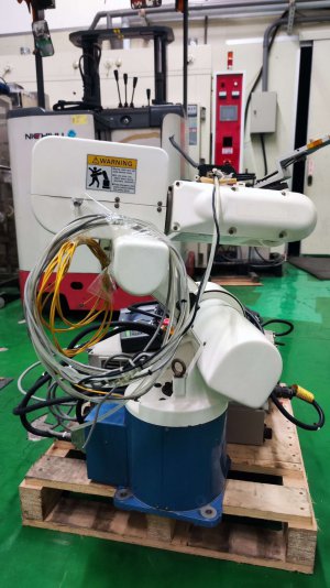
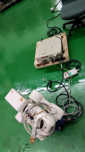
It's still very rudimentary now I haven't carefully cleaned the outer shell of the robot and sorted out the wiring.
Now the power supply part has a reliable connection between the controller and the robot's ground.
I will upload photos of the latest configuration and the results of subsequent calibration attempts in my next reply !
I use it in my dad's factory.
He helped me connect the power supply and help me troubleshoot hardware problems.
He does metal processing and the like.
I had just graduated from college, majoring in electrical engineering, but I was good at writing programs, so my dad asked me if I was interested in programming robotic arms and wanted me to try to move these two robotic arms that had been left for a long time.
Maybe it can have some applications in the future, I am also looking forward to it !
But of us is not familiar with robotic arms, and no one we know has relevant experience.
The only content I found about this robotic arm on the Internet is the repair process you shared, and there are detailed instructions and debug process.
It really helped me a lot in installation, use, and debugging.
It also gave me a deeper understanding of the robotic arm.
Thank you again for your help!
There should be no other manuals, right?
Yes I have replaced the controller battery and checked the polarity and voltage, I will check again to make sure that part is ok.
My bad, I forgot to explain my setup first, my setup is as follows:
1. Robot Arm: VS-6354C (V9.58)*2
2. Controller: RC3-V6A (with Operation Panel)*2
3. Teaching Pendant (410100-0560)*1 (The original 410100-0110 and -0120 cannot be purchased on ebay, so I bought one that looks the same and has six axes controll batton. Everything is working fine now)
4. Cable: Power Cable *2, Motor Cable *2, Encoder Cable *2
5. Other: Suction cup installed on J6*2, fiber amplifier used with the suction cup (Keyence FS-N11N, originally seems to be used to sense the distance of the workpiece)*2
Apart from the above, I have no other accessories, cables, connectors, floppy disks and the like.
I changed the battery because after turning on the power for the first time, many errors popped up.
According to the error code instructions, I directly replaced the batteries of the controller and arm (the same specifications and voltage as the original ones).
I Forgot to measure the original battery voltage first.
But turning the power on again did eliminate those error codes.
It turns out that my memory clearing program only did the [BCLR] [123] part, and I didn’t see the [1409] part required in the Owner’s Manual.
This may also be the cause of Error 106.
After Error 106 started to appear, I also measured the voltage of the controller battery and each Robot Encoder Backup Battery again, but I have not yet carefully measured whether the motor connector of each joint of the robot has the correct voltage.
I will measure again to ensure this part is normal.
It is true that I have not reconfigured PLIM, NLIM, and RANG.
This may also be the reason why I cannot calibrate successfully.
I only suspected this when I re-read the Owner's Manual a few days ago.
According to your explanation, the probability is very high.
I may be able to calibrate the J6 using the suction cup base mounted on it, it should be feasible
OK, thank you for your reply and detailed step-by-step instructions.
This really helps me a lot, otherwise it might take me several months to figure out what the problem is
Certainly! I'd love to share photos of my setup!
This is a photo taken last month when the calibrate started:


It's still very rudimentary now I haven't carefully cleaned the outer shell of the robot and sorted out the wiring.
Now the power supply part has a reliable connection between the controller and the robot's ground.
I will upload photos of the latest configuration and the results of subsequent calibration attempts in my next reply !
I use it in my dad's factory.
He helped me connect the power supply and help me troubleshoot hardware problems.
He does metal processing and the like.
I had just graduated from college, majoring in electrical engineering, but I was good at writing programs, so my dad asked me if I was interested in programming robotic arms and wanted me to try to move these two robotic arms that had been left for a long time.
Maybe it can have some applications in the future, I am also looking forward to it !
But of us is not familiar with robotic arms, and no one we know has relevant experience.
The only content I found about this robotic arm on the Internet is the repair process you shared, and there are detailed instructions and debug process.
It really helped me a lot in installation, use, and debugging.
It also gave me a deeper understanding of the robotic arm.
Thank you again for your help!
- Joined
- Mar 26, 2018
- Messages
- 2,724
Sent you an PM. I'll get you all the manuals I have, but the package is too big to post on here directly. I also have the original software.
VERY cool! Thanks so much for sharing. I don't think I found any resources online when I started this project. These seemed quite rare outside of Asia.
I have confidence you'll get this running.
I'm curious how you can turn the robot on without the INPUT connector plugged in. There is a robot stop input that must be enabled on that connector or the robot will not power on.
If you get a chance, I'd be curious to know how many hours your robot has been running. Owners manual A page 3-28 has the procedure.
These robots are quite old, but surprisingly capable. I've had a lot of fun programming them. The document package I will send you has some example programs.
Good news!
I successfully completed the calibration!
I followed the steps you told me to calibrate from scratch:
1. Execute the two memory clearing procedures you mentioned. >Restarting the power did not show any errors again.
2. Configure PLIM, NLIM and RANG. The values of PLIM and NLIM are based on the default values in the owner's manual, and the value of RANG is based on the sticker on the robot arm. >Completed successfully.
3. Use a shorting jumper to reset the encoder reset pin of each axis, but the error code displayed each time it is reset is not 771~776, but seems to be 411~416. I don’t remember exactly.
4. When executing ALL AXIS CALSET RUN, error 471~476 will appear in each axis at first. This may be because when I was doing calibration before, after the motor released the brake, each axis was adjusted to the RANG hard stop position.
Execute ALL AXIS CALSET RUN again, moving each axis slightly away from the hard stop during the process, then press [SURE] and then press [REC] to complete successfully.
5. Press [MANUAL][MOTOR ON]>[CAL]>[START], it displays [CAL OK], enter [SP]>[100]>[ENT], then I hold down the deadman switch and press + J1 ~J6, it seems that it was not pressed - J1~J6, I don’t remember much, but J1~J6 did not respond or move at all, and then displayed error 71~76.
After turning the power back on, move each axis slightly, and try again with the same result. According to the error code table, it should be a software limit issue.
I will reconfigure PLIM, NLIM and RANG tomorrow, and re-execute ALL AXIS CALSET RUN, and check the running time of the robot arm. It may be a numerical problem or excessive slight adjustments that cause the numerical values to fail to match. I hope I can get it running tomorrow.
This is the setup now (I only use one set, bottom left and top right):
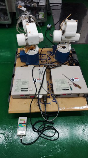
(the INPUT port of the lower right controller was accidentally damaged during soldering, and I am waiting to replace it with a new INPUT port)
And the way I connect pin1&3 on the INPUT connector :
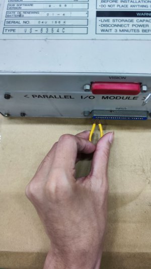
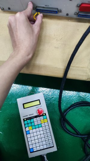
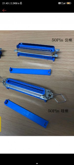
It is expected to buy a 50 pin male connector for subsequent use and connection:
I successfully completed the calibration!
I followed the steps you told me to calibrate from scratch:
1. Execute the two memory clearing procedures you mentioned. >Restarting the power did not show any errors again.
2. Configure PLIM, NLIM and RANG. The values of PLIM and NLIM are based on the default values in the owner's manual, and the value of RANG is based on the sticker on the robot arm. >Completed successfully.
3. Use a shorting jumper to reset the encoder reset pin of each axis, but the error code displayed each time it is reset is not 771~776, but seems to be 411~416. I don’t remember exactly.
4. When executing ALL AXIS CALSET RUN, error 471~476 will appear in each axis at first. This may be because when I was doing calibration before, after the motor released the brake, each axis was adjusted to the RANG hard stop position.
Execute ALL AXIS CALSET RUN again, moving each axis slightly away from the hard stop during the process, then press [SURE] and then press [REC] to complete successfully.
5. Press [MANUAL][MOTOR ON]>[CAL]>[START], it displays [CAL OK], enter [SP]>[100]>[ENT], then I hold down the deadman switch and press + J1 ~J6, it seems that it was not pressed - J1~J6, I don’t remember much, but J1~J6 did not respond or move at all, and then displayed error 71~76.
After turning the power back on, move each axis slightly, and try again with the same result. According to the error code table, it should be a software limit issue.
I will reconfigure PLIM, NLIM and RANG tomorrow, and re-execute ALL AXIS CALSET RUN, and check the running time of the robot arm. It may be a numerical problem or excessive slight adjustments that cause the numerical values to fail to match. I hope I can get it running tomorrow.
This is the setup now (I only use one set, bottom left and top right):

(the INPUT port of the lower right controller was accidentally damaged during soldering, and I am waiting to replace it with a new INPUT port)
And the way I connect pin1&3 on the INPUT connector :


It is expected to buy a 50 pin male connector for subsequent use and connection:

Last edited:
After I reconfigure PLIM, NLIM and RANG, and re-execute ALL AXIS CALSET RUN, The robotic arm can finally move!
I first push each axis to the RANG position, then turn on the motor power, and use [DISP] to confirm the current angle of each axis.
Then set the PLIM of J1~J6 to be the same as RANG. Only for J2, set the NLIM to be the same as RANG, and RANG is set exactly according to the angle displayed in [DISP].
All other values are set as listed in the owner's manual.
The original angle in the manual and the RANG listed on the sticker are too small. After setting it according to the value displayed in [DISP] and recalibrating it, the arm can move normally.
If necessary later, I can also adjust PLIM, NLIM, and RANG again to limit or increase the angle at which each axis can move.
Unfortunately, after performing a complete memory clearing procedure, the robot arm's running time was also reset. I will then check the running time of another set of robotic arms and share it.
Thank you very much for your help, which allowed me to successfully complete the calibration and repair of the robotic arm. What you mentioned are the most important steps. Without your instructions, I would not have been able to succeed.
If I have any new progress or attempts and applications in the future, I will leave a message to share with you.
Below is a video I recorded of controlling the robotic arm:
Last edited:

