Mike's 6-Axis Articulated Robot

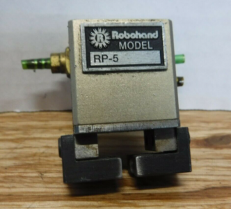
Picked up a basic 2 jaw parallel gripper for the robot. It was $20 on eBay so I figured why not.

1650481313363.png

This particular gripper is very tiny, measuring an inch by an inch and a half. The jaws can stroke 1/8" and apply a maximum of 40lbs of clamping force. This will be perfect for lightweight gripping tasks.

Once things are running, I think I'm going to machine some tooling to allow the robot to do pick and place assembly with Lego pieces. Should be a good test of the dexterity and accuracy of the robot.
 
Electrician comes tomorrow. Spent just a little bit of time over the weekend working on the transformer sled for the robot.

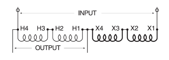
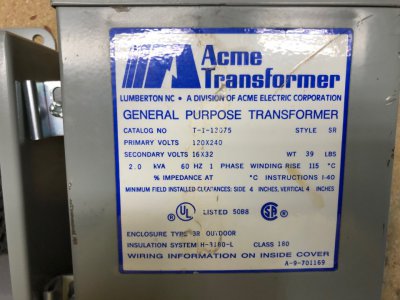
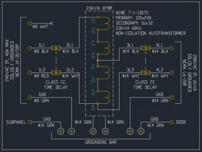
The transformer is an ACME 2kVA autotransformer. Pretty cool thing honestly, first time I have used one. Takes in a whole range of input voltages and spits out 16 or 32VAC. This can be tapped to add or subtract the 16 or 32VAC from the original supply. In my case I'm doing 240V - 32V = 208V which is within the robots 210 +/- 10%. The tapping of the transformer looks like below.

1650892756330.png

image219.jpg

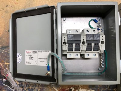
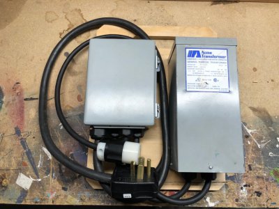
I'm setting this up to be able to plug into any 30A 240V outlet in my basement. Per NEC, since my supply breaker is larger than 250% of the primary current, I need both primary and secondary fusing on the transformer. I got my hands on a little 8x6 Hoffman enclosure to hold these. I had to make a subpanel from some sheet metal I had hanging around. My shop is set up pretty efficiently for making panels so I was able to pop this one out in about 1.5 hours. There are two banks of fuses, input @ 10A and output @ 15A, both time delay Class CC. There will be two pigtails with a NEMA L14-30P (input) and a NEMA L6-20R (output). Waiting for some cord grips to come in the mail which I'll use with some SO cord to wire between the box and the transformer. I also am in the process of making the plywood skid that will hold both of these and hang on the wall.

image218.jpg

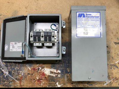
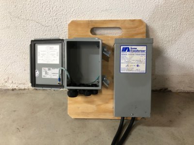
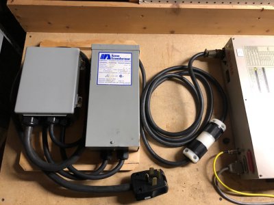
And the pair side by side as they'll be mounted.

image217.jpg

I also got the J5 gearbox cleaned out and re-greased. This one was in pretty good shape, but now it has the compatible grease for what I have in the grease gun. I still need to do J6 (easy to access) and J1 (very hard to access). I might revisit pulling the flex spline from J2 since it was the one with the most grit in it - must've been used more than the others. The pictures are nothing special so I'm not going to bother sharing them.

Before I power this on, I need to do the following:
  • Verify all connectors inside the robot are secure
  • Finish ohming out the power connections to the motors (this verifies my DIY motor cable). I'm 2/3 done.
  • Verify the polarity of all (6) battery board connections. Getting them flipped will burn out the encoders!
  • Solder the lithium primary batteries to the battery board and install.
  • Verify I tightened the Denso servo drive module securely to the control box (I removed one for inspection)
  • Put some sort of filter paper over the fan intake and exhaust
  • Verify voltage on controller battery
  • Verify pinout of DIY teach pendant cable against sketches from eBay sellers. Verify no shorts between pins.
  • Verify supply voltage at 208V
  • Wire the input power cable. Triple check input voltage connections
  • Install ground conductor between robot and controller.
  • Pray to the good lord that the input MOVs don't blow up when I power it on and that I didn't screw anything else up.
 
Finished the transformer sled. Electricians got about halfway done yesterday. Hope they can finish today. They're doing a lot of work, glad I hired it out.

Made up a simple 3/4" thick plywood sled on the table saw and miter saw. My woodworking skills are garbage and table saws scare the bejesus out of me. I used a hole saw and a jigsaw to cut the handle. The outline was drawn in CAD and transferred to the board with a printout.

I didn't have a step drill big enough to cut the 3/4" and 1" trade size knockouts (1.125" and 1.375" respectively) and didn't want to buy the $80 tool. Instead I got 2 hole saws. This was a terrible idea and while they did cut holes, the edges were super jagged, oversized, and it scratched the crap out of the paint all around the hole. Not happy but it is done.

McMaster Carr delivered some cord grips to me to fit these new knockout holes as well as the punched knockouts on the bottom of the transformer.

I wired the taps inside the transformer per the manufacturer data sheet, but I'm going to be nervous plugging it in.
image223.jpg

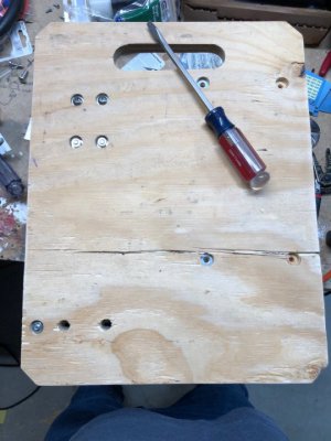
I used a 5/8" spade drill to counter bore the back of the board for a washer and nut for 1/4" bolts. This way the back of the board is flat and smooth. Access holes were drilled to install the small cover screws for the bottom of the transformer once it was mounted.

The transformer was particularly annoying to mount since it didn't have mounting holes. I ended up fabricating a steel bracket with through holes for 1/4" bolts on the bottom. The transformer could be slid onto the bracket using the hanger on the rear. Once the transformer was on, I could screw 2 screws from the back into tapped holes at the top of the bracket to fix the bracket. There is one hole at the bottom of the transformer that I could bolt through and this rigidly locked the transformer to the board.

image222.jpg

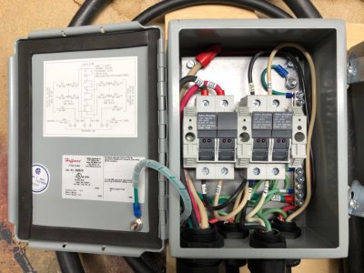
Here is the finished wiring. I can hook this up to any 240V supply (up to 40A on the panel breaker) and get 208V on the output. The Class CC time delay fuses protect the transformer and secondary wiring.

image221.jpg

Here is the finished sled. NEMA 14-30P plug on the input, which matches all my machine tools, and NEMA L6-20R inline receptacle on the output which matches the power cable for the robot.

image220.jpg
 
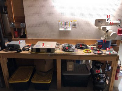
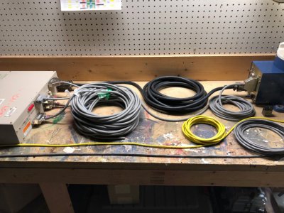
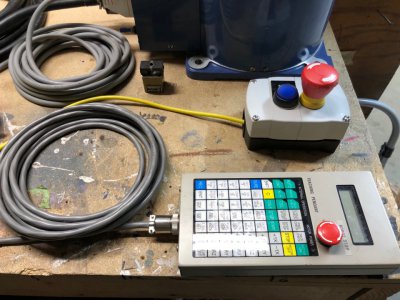
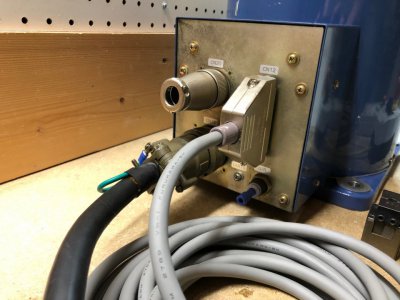
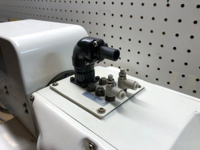
Not much to share new, but I did lay out the whole robot system on the workbench. Fun to look at.

Added labels:
1) Transformer sled, 240V input, 208V output, 2.0kVA
2) Robot power cable, 3'
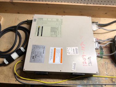
3) RC3-V6A Robot controller
4) PLC interface cables. (1) Input Cable, (2) Output Cables, (1) Valve Command Cable
5) Robot motor cable, 20'
6) Robot encoder cable, 20'
7) STOP cable, 20'
8) Pendant cable, 20'
9) Teach pendant
10) ESTOP console
11) VS-6354CM Robot
12) Robohand Gripper, RP-5
13) Compressor, regulator, filter, tubing (To be added)
14) End of arm tooling connector, 10 pin
15) Pneumatic fittings for end of arm tooling

image224.jpg

image226.jpg

Thank God I didn't pay that much for it!

image227.jpg

image228.jpg

image229.jpg

image230.jpg

image231.jpg

That's all for now. Next step is to finish me power on checklist and wait for the electricians to get their work done.
 
With the whole system put together, I had a couple of thoughts about what I DON'T have to go with this robot.
  • I have the WINCAPS software for offline programming (not sure how this works) but it needs Windows 3.1, '95, '98, or might be compatible in Millenium Edition (ME). Windows XP, 7, 8, 10 are not supported. It needs 8MB of memory and 3MB of hard disk space :p. I could likely spin up an old windows Virtual Machine on my laptop.
  • I do not have an RS232 cable to connect between the offline programming computer and the RC3-V6A controller. The user manual shows the desired wiring, so it would be very easy to make one.
  • I do not have the floppy disk loader. This is a real bummer to be honest. This would let you save user programs and settings to floppy disks and reload them. Apparently these were not very popular and were not sold much in the US. As a result, the second hand market is barren. The cable and protocol are not described in the manual so without a working unit to reference, I'm not sure I could make a generic floppy disk drive work. Without this, my programming options are either to write the entire program on the teach pendant, or program them offline with the WINCAPS software. The robot controller has some internal memory for multiple programs, limited to:
    • Program Step memory limit: 8000 steps
    • Position data point memory limit: 1200 points (cartesian + joint angles)
    • The manual doesn't exactly tell you how many programs the controller can hold, but there are 7 inputs for program select, plus a parity check, so I would assume it can store at least 128 programs.
  • The RC3-V6A can connect to a printer over RS232 for the purposes of printing programs, variables, and positions. This uses the same port as the offline programming computer. Again, the cable specs are in the manual, so this would be easy to add. Would need to find a printer, or a virtual printer interface, that could support ASCII RS232 printing.
  • The RC3-V6A can connect to a uVision-15 robot vision system which includes a standalone control box, teach pendant, camera, and monitor. This is an entire separate system from the robot and I do not have the manuals. The robot manual makes a brief statement that the system can do position measurement, shape recognition, and part distinguishing. Pretty impressive for some late 90's tech. There is one control box on eBay for $99 and a teach pendant for $250, but no camera or monitor (all BNC coaxial). I don't really have any use for this, but would be interesting to play with if I already had the robot working
 
Electricians are all done! Shop is back in business (sorta - lathe needs to be leveled and CNC needs assembly).

Wrote a detailed checklist for starting up the robot. Don't want to rush and break it because I forgot something stupid. I'm mostly concerned about mis-wiring on things I've messed with. Here is the checklist:

DENSO VS-6354CM Robot Startup Checklist

- Verify all connectors inside the robot are secure
  • J1
  • J2
  • J3
  • J4
  • J5
  • J6
- Finish ohming out the power connections to the motors, printed
  • J1
  • J2 (DONE)
  • J3 (DONE)
  • J4 (DONE)
  • J5
  • J6
- Verify the polarity of all (6) battery board connections, printed
  • J1
  • J2
  • J3
  • J4
  • J5
  • J6
- Solder the lithium primary batteries to the battery board and seal in plastic

- Solder the lithium primary battery for the controller to the connector, seal in plastic

- Verify I tightened the Denso servo drive module securely to the control box (DONE)

- Put some sort of filter paper over the fan intake and exhaust (DONE)

- Verify voltage on controller battery: _____3.06_____________VDC (3.0VDC Nominal) (DONE)

- Verify pinout of DIY teach pendant cable against sketches from eBay sellers. Verify no shorts between pins, printed (DONE)

- Electricians finish electric install (DONE)
  • Verify 120V at all outlets (DONE)
  • Verify 240V at all outlets (DONE)
  • Verify 120V to Neutral on both phases of 240V outlet (DONE)
  • Verify solid grounding at all outlets (DONE)
- Have electricians verify transformer wiring per manual (DONE)

- Disconnect transformer output from RC3-V6A. Energize transformer, verify supply voltage at 208V (DONE)

- Wire the input power cable. Triple check input voltage connections. (DONE)

- Disconnect power cable from RC3-V6A controller. Attach power cable to transformer. Energize transformer. Verify voltage between pins A & B ____215_______VAC (210 VAC +/- 10% permissible). Verify 0V on Pins C & D. Verify continuity between pin D and GND. (DONE)

- Install ground conductor between robot and controller. 10 AWG minimum

- Wire STOP circuit to ESTOP box. (DONE)

- Pray to the good lord that the input MOVs don't blow up when I power it on and that I didn't screw anything else up.

- Assemble entire robot system and verify all connections secure

- Apply voltage to RC3-V6A per printed procedure. Power off immediately if the following are not met:
  • Verify the indicator lamp is illuminated
  • Verify the teach pendant screen displays “T-PENDANT Ready”
  • Verify the fans spin
- Execute the Encoder Battery Replacement Procedure, printed

- Execute the Controller Battery Replacement Procedure, printed

- Execute the Encoder Reset Procedure, printed

- Execute the CALSET Procedure, printed

- Verify the SETPRM Values (PLIM, NLIM, RANG) for all axes. RANG is not described in the manual, but should follow NLIM6 as you cycle through the list. These values are printed on the body of the robot. Verify the PLIM and NLIM values against the default table in the procedure, printed

- ONLY IF NECESSARY, complete the RC3 CLEAR DATA procedure, printed

- Perform the Set Date & Time Procedure, printed

- Address any error codes, if present. Error code manual printed
 
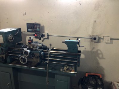
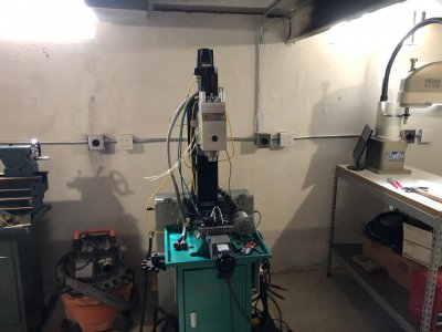
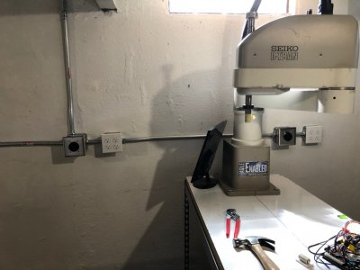
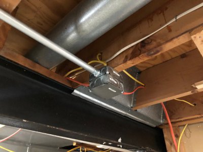
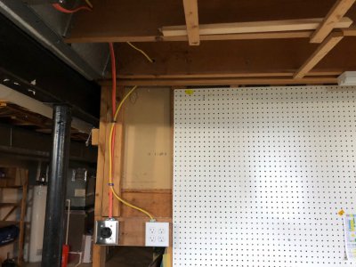
Here's the electric install and a quick shop tour. The machines are in a sorry state right now. Each one deserves a few days to get set up and aligned. Each machine gets (1) 240V 4-wire 30A outlet and (4) 120V outlets. I have (4) machine stations along the wall, and (1) at the workbench.

Enco 110-2033 (12x36 lathe)
image234.jpg

G0704 CNC mill
image236.jpg

Seiko D-Tran TT-8800 SCARA robot (1999)
image235.jpg

Overhead junction for power
image237.jpg

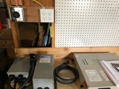
Outlets on workbench wall. They didn't do the prettiest job here but it is OK. Maybe I'll do my own conduit at some point.
image238.jpg

This will be where I do most of my testing of the Denso robot.
image239.jpg
 
Back
Top