Machine Tool Alignment Gauge Plans

Hi Ron.
You found a useful looking version of the Kingway Alignment Tool.
Use those keywords on YouTube, and have a feast of viewing.

The original is in the patent (expired). Alternative versions have happened since, but the patent does also contain the detailed instructions for using it in all sorts of modes. I include it here

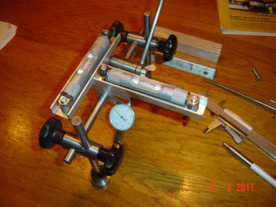
Here is a picture of one that can be made up just from turning, a couple of short pieces of aluminium U-section, and eBay knobs.
Alignment detector.jpg

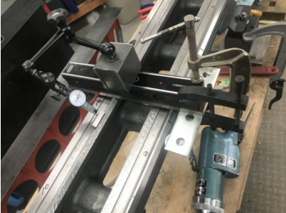
Now have a smile at Rex Walter's "Ghetto Kingway" using a couple of washers superglued to a piece of metal, and an assortment of clamps.
:)
Ghetto Kingway-RexWalters-version.png

I get it that chasing down the instagram thread is just not viable. If you do have a mind to make up one, I include here a text file for the dimensions for two size versions. It depends on how big your lathe is. The file is a simple .txt, but you might need Notepad+ or something like that if using Windows.
 

Attachments

  • US2761217-Kingway Alignment Tool.pdf
    748.6 KB · Views: 103
  • US Kingway Alignment Tool Dimensions.txt
    1.9 KB · Views: 99
Hi Ron.
You found a useful looking version of the Kingway Alignment Tool.

:)


I get it that chasing down the instagram thread is just not viable. If you do have a mind to make up one, I include here a text file for the dimensions for two size versions. It depends on how big your lathe is. The file is a simple .txt, but you might need Notepad+ or something like that if using Windows.
Thanks, the school link is to a set of pdf plans. Was going ask you if you think I should pull the topic, but as you seem to consider it useful, I'll take your opinion. I've sorta followed Rex's journey, but missed the tool LOL. Will go read up on it.
 
I will stick with the proven method, turning a test bar.
Jim, thanks for reminding us there are less time and equipment consuming options. This is simply another one of many. I know a search of Rollie's Dads Method will turn up many who use it. At least I think it's for the same purpose.

Ron
 
There is a difference between the base aim of using (any one of several) methods to set up a lathe to not turn tapers, and what you might go through to measure up the state of the lathe surfaces relative to each other, with the aim of something more profound - like scraping the worn ways.

We also sometimes lose sight of what is "leveling" a lathe to get the ways aligned, and the different purpose of using levels to "measure deviations" and determine the condition of worn surfaces. A lathe does not actually have to be level, so long as all the ways and spindle and tailstock align, but in most situations, a horizontal level reference via a spirit level is the only starting point reference we have in order to get all the heavy deflecting parts in the correct position to each other. Highly convenient to use gravity this way. Lathes fixed into ship frames are tipping about all over the place all the time, and they work just fine, because the ways were set parallel to each other and the spindle axis, using the ship's construction reference when it was fixed in.

In theory, you could set up a lathe to some degree not level, just so long as the amount not level is the same everywhere, so that all the surfaces end up correct relative to each other

Rollie's Dad's method works, and is a way to get you there without a starting reference of known accuracy. It is a clever method that converges to correct, starting with nothing, but there are simpler faster ways to get there. If you start with a test bar already made to micron accuracy, and a DTI, you can find out a lot very quickly. Making your own dumbell test bar, and discovering the diameters are unequal brings the reference back to a micrometer - and by the time you are done, you have also made yourself a sort of test bar with two short sections.

One of the best, most educational explanations I have seen is from Quinn Dunki using glued together cocktail sticks.
How to Align Your Lathe

If your lathe has been standing with winding-twisted ways, the steel will have taken a set, and somewhat de-stressed into that shape. If you set about straightening it up, perhaps testing by using a level, or adjusting on the floor supports to get your test bar turnings to perfection, you may have it straight, but you will have re-introduced a stress to do it. Then over a day or two, the casting will "fight back", and you find you have to tweak it a little until it settles. I have read a tale that one can get a re-leveling to settle quickly by giving the end of the bed a couple of smacks with a hammer, but I don't know if this is true. It sounds a bit like folk who hang camel-back straight edge castings from one end, and then "ring" them with a hammer.
 
Last edited:
I made a Kingway device from a kit provided by Rich King, it is vastly superior to the plans above, they came in 3 different sizes, mine is the largest size, but I would like to make one of the smaller sizes as well.
 
Thanks Graham. I have a level and do understand the purpose is to align the ways. The best example I've seen being a lathe on a ship will only rarely be "level."

I'm trying to not get pulled into a discussion of "best". Best, IMHO, being very subjective, opinion, without minimizing variables, defining screening criteria, giving each one a weight, validating the logic, and not changing the criteria when the results aren't what you predetermined they "should" be.

IMHO the purpose of a forum is to share information and help others. Hence the title "The friendly forum." That was my only reason for the posting, not to open a lecture on "whatever".

Like the tool and use it. Offer constructive suggestions with examples/links (thanks, I'm actually a small patron of hers and missed this) of other options. Offer "why" you think something else is an option. Or ignore it as having nothing constructive to add. But I won't bother again. Too many other things to do with my time.
 
The Kingway is much more useful with application to many different slideway geometries, including vee and inverted vee ways and square ways, nearly any way geometries used on machine tools, and has level vials in both cross and longitudinal directions so that in lathe leveling both cross leveling and sag can be detected at the same time.
 
Thanks Graham. I have a level and do understand the purpose is to align the ways. The best example I've seen being a lathe on a ship will only rarely be "level."

I'm trying to not get pulled into a discussion of "best". Best, IMHO, being very subjective, opinion, without minimizing variables, defining screening criteria, giving each one a weight, validating the logic, and not changing the criteria when the results aren't what you predetermined they "should" be.

IMHO the purpose of a forum is to share information and help others. Hence the title "The friendly forum." That was my only reason for the posting, not to open a lecture on "whatever".

Like the tool and use it. Offer constructive suggestions with examples/links (thanks, I'm actually a small patron of hers and missed this) of other options. Offer "why" you think something else is an option. Or ignore it as having nothing constructive to add. But I won't bother again. Too many other things to do with my time.

Stumbled across this and looks interesting. From Laney College, Oakland CA. Machine Tool Alignment Gauge Plans [pdf]

Sadly the instructions are buried in an Instagram thread but I think I have provided a link to the posting.

Ron
Having a King alignment gage and knowing how to use it are different things, I have an original, Medium size.
Thanks, the school link is to a set of pdf plans. Was going ask you if you think I should pull the topic, but as you seem to consider it useful, I'll take your opinion. I've sorta followed Rex's journey, but missed the tool LOL. Will go read up on it.
The advantage of the King gage is with adjustable levels overall level is not required, comparative readings are easily made but some of this can be misleading so experience is needed.
 
Back
Top