Machine limit switch zero and user defined zero for parts?

Jake2465

Registered
Registered
Joined
Dec 27, 2017
Messages
340
So, if I am understanding this concept correctly, a CNC mill will do a home limit switch routine and then it sets that as the machine zero. But, that would probably be off in the corner of the table somewhere and that is not terribly convenient for a part zero. So, when someone wants to use the center of the mill table and locate part zero there, how is that normally done? And I am not referring to the act of using an edge finder to find the corner of a part, but rather this relationship between the machine's home zero and part zero.
 
This may vary from controller to controller but for the two that I have worked with, Mach 3 and PathPilot, You would select your coordinate system (G54, G55, etc.) and move the table to the position you want as your work zero and zero your axes. Alternatively, you can enter an offset for any non-zero position. G53 will put you in the machine coordinate system.
 
My mill has sticky limit switches that don't repeat well. So, whenever the control tried to do a home routine, I would get limit switch repeatability errors and so I disabled the home routine. So, whenever I would make a part zero I would simply zero the DRO in that same spot. Since this mill does not really run any production, and my part zero position tends to change from part to part, not having a home routine has not really slowed me down. The only thing to watch for is that if I am about to go home for the day and I want to shut the machine down, I have to remember to jog the table back to the part zero point before I shut it down so I don't lose it.

I'm going to watch some YouTube videos on those codes you mentioned.
 
Jake,

RJSakowski has it exactly right. I'll just add a couple things in the hopes of confusing you ;)

1. Machine coordinate system zero can be anywhere, but this depends on the machine/controller. Every 'store-bought' CNC I've seen/used the machine zero point is defined by the manufacturer and is generally at the limit of the axis travels. On my lathe, the home position is the turret/slide as far from the spindle in Z and X as possible, but the "Machine Zero" point is defined by the manufacturer as the centerline & face of the spindle - very annoying.

However, in the DIY world it may be possible to change the location in the controller settings.

In my controller I have 'write offset' as an available option field in my axis settings. If I use this the machine homes, finds the switch, and then writes the offset number in the machine DRO - not '0'. This means I can have machine zero anywhere within the machine travels.

Example 1: my mill Z switch is at the top of travel and I have no zero offset. So all Z movements are negative numbers in machine coordinates (not work coordinates).
Example 2: Big plasma I just built has the homing switches at the far end of the table (away from the operator). But I write an offset on homing equal to the length of travel in Y. This means machine zero is closest to the operator and to the left in X/Y so all torch positions are positive numbers.

2. There are, in addition to G54/G5xx Work Coordinate Shifts, many other ways to 'zero' a part or location within the machine envlope. This also depends on the controller, but there are temporary work shifts (G52), pallet work shifts (Hxx for Fadal), and may others where the OEM controller manufactuer wants to add features for the end user.

Fix your switches, and maybe replace them with something more repeatable. Having a homing sequence makes life so much nicer even if the switches are only good to a couple 'thou. You can create parking positions for unloading/washdown, or for me I've got a parking position where the spindle is right over the centerline of my 4th axis. Saves time touching off, and the parking positions are easily programmed & recalled with a user-edited M-code.

I've got a bucket of old proximity switches. They're various NPN NO & NC's with some at 5v and a few up to 24v. I could send you a fistfull to play with and make sure you get thee working ones.

-Ralph

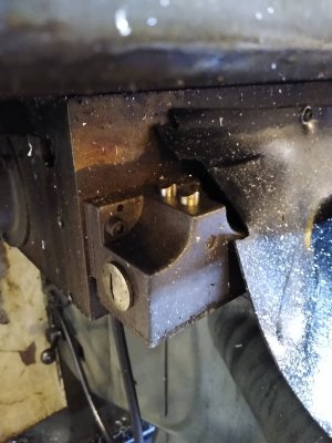
The switches that I have look like big blocks with vertical plungers on them for the X and Y. So, I am not sure If I could easily get direct replacement switches or not. I may have to whittle out some adapters if a new set is to be used.

I was asking about offsets because I may have a job that will end up having to make full use of a mill table. I will probably gang 4 vises on the table to work 4 parts at a time. Basically, two vises will do the first setup and the other two vises will be for the part flip so the backsides can be machined. With a setup like that, I definitely do not want to have to fool with finding my part zeros all the time. I would probably have a high likelihood of the parts coming out inconsistent.

up until now, I have only really used one vise on the mill at any given time and just a G54.
 
That's an easy one:

1. Mount your vises, and attach a work-stop on each vise so the stock (or OP2 part) goes in the same way each time.
2. Find X/Y/Z zero on vise #1. Set G54 X/Y/Z to 0.
3. Move to vise 2 and find zero. CHANGE TO G55 and set zero. Switch back to G54 and write down the offset numbers for Vise 2.
4. Repeat for vise 3 & 4, using G56 and G57

You now just have to touch off vise #1 and your machine will remember the amount to offset for the other vises. If the machine throws up, you have the offsets written down for that vise spacing and part run.

If you're using two vises to hold one part, its easier - just do vise #1 and set vise #3 as G55.

EDIT - If that wasn't clear, let me know and I'll try again.
 
Take a photo of your switches and post it. We'll see what you need and can help replace or retrofit.
 
I am pretty sure I am understanding the general concept. It sounds like it's pretty straight forward. And really the only thing that would change between the offsets is the X coordinate. Since the vises will probably be keyed into the T-slots, they should be the same... Well, I take that back. The Z heights on the last two vises would need to be different because the flipped parts will need to be held in their own special fixtures and that will raise the Z height on those a bit.

I will get some pictures of those switches.
 
One of the early modifications that I made on my Tormach 770 was to add optical homing to all three axes. I have repeatability of my home coordinates to +/- .0001".
 
Here is a picture of the limit switch my mill uses.
 

Attachments

  • limit switch.jpg
    limit switch.jpg
    550.9 KB · Views: 20
Back
Top