Lufkin Holddowns. How Are They Used?

Wouldn't steel balls with a ground flat or round aluminum wire/rods do the same thing as the Hold-Downs?
 
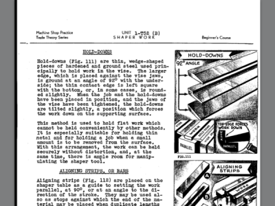
No. The rear angle of the hold-down (that is the thicker of the two edges) is ground such that it is not 90 degrees. In use, the slight more-than-90 angle on that thicker edge causes the hold-down to want to angle down towards the bed of the vise, and in doing so it takes the part with it. When you use two hold-downs with the part in between, they draw the part flat down to the vise bed as well as pinch it between the jaws.

-frank
 
Exactly correct,francist. I have hold downs down to 2" long. The 2" ones may have been shop made by a GOOD tool maker. They are usually 6" long. The 6" kurt vises have flat areas about 2"wide on either side of the center area,which is where the screw lives.

I have used that little 2" wide area to hold small jewelry master models. Just as the jaws of the vise reach the thick side of the hold downs,they begin to cock up as the vise is tightened. The thin side,which is against the work piece,rotates downwards,pulling the work piece down against the vise. Your work piece needs to have 2 parallel sides,opposite each other. If mine doesn't,I just super glue them down,as I mentioned before. Since I'm only using end mills about 1/32" wide,maybe up to 1/8" wide,the glue is plenty strong enough. I never have had a glued workpiece come loose.

To be functional,your hold downs need to be crisp and accurately ground so that the thin side has sharp edges so they grasp the work as it is being pulled downwards. This has to be done in a surface grinder,or a tool and cutter grinder. I have never seen a pair of hold downs that had dulled corners. They aren't a tool that is used often,and are made of good tool steel that is hardened.
 
They also let you mill down that side between the jaw and the material. There not utilized much anymore in the old shops every machinist had several in different sizes. We made sets in vokie when I went in the early 70s. Our shop teachers had us make tools for grades we had two tool & die , + machine shop.
The tool shop had the heat treatment room and grinding room. Even cylindrical grinder . We made some Kool items , a gear case with sliding mesh to shift gears. Splines and gears all made by students. Class projects we all got to keep the tools we built.
 
I wish I could make out the pics better. For some reason, I just don't see how they are working. Someone have a better pic?
 
Does this help? Not the best, agreed, but what I could come up with at the moment. I know it's a bit hard to get your head around how they're oriented, but once you get the theory they make perfect sense.

This was excerpted from one of my shaper references, and that's where I see them mostly. I suspect they may have dropped out of favour at the same time as the shaper did? They don't seem to be commonly referenced in modern milling machine practise. Just guessing at that though. Maybe some of the more experienced guys who worked in shops as shapers went out could comment.

-frank


image.png
 
Back
Top