Lathe repair advice needed

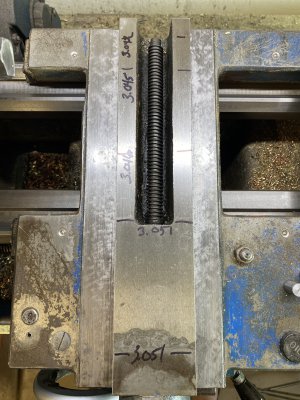
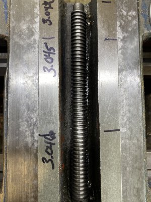
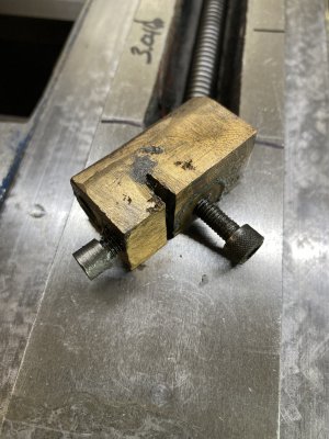
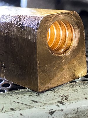
The “crack” is some kind of casting flashing it looks like. There are oiling holes all over these slides. They’re all patent and i’ve kept it all oiled since I acquired it a year ago. Who knows how it was treated in the past. It’s not a fancy lathe. In my first post I included a link with some info about it. It’a a 1980 year model lathe made in Taiwan. I don’t see any visible cracks in the saddle or cross slide or gib. I don’t know how to remove the top of the carriage or I’d take it to the shop with me today and magnaflux all the parts. I can do the cross slide and gib today though. The brass nut is messy enough I can’t appreciate its condition. I’ll wash that in the parts washer at the shop today. Not sure how that set screw is useful for any kind of adjustment.... it’s tightened in the back of the nut already. The screw looks good. It’s clean and straight. No crazy wear noted at all, but the brass nut might be well worn inside.

I posted images with measurements. Sorry they’re not a good resolution, but I have no way of reducing it without getting on the computer and figuring out a way to do that. I’ll kwep practicing.

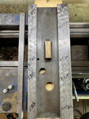
Also, I’m not sure how valid my measurements are under the cross slide. It’s tapered so that seems useless. The larger numbers on the left of that image are without the gib in place. With the gib it place it’s certainly not straight either.

Mr. King, I’ll do some additional measurements with the dial indicator that you mentioned either this evening or tomorrow. It’s about time I got to the shop and got busy for the day.
 

Attachments

  • BBC286DF-6DB5-453F-80FE-24D897BC02AD.jpeg
    BBC286DF-6DB5-453F-80FE-24D897BC02AD.jpeg
    2.8 MB · Views: 14
  • BAFF5BB3-F8BD-4CB2-B52B-8F1B9579AD2D.jpeg
    BAFF5BB3-F8BD-4CB2-B52B-8F1B9579AD2D.jpeg
    2.9 MB · Views: 9
  • 3A43658C-B8D1-4EAC-BF03-8C1ECC575269.jpeg
    3A43658C-B8D1-4EAC-BF03-8C1ECC575269.jpeg
    2.8 MB · Views: 10
  • 3498B7D3-A81C-479F-8A15-6FF2AEA16D08.jpeg
    3498B7D3-A81C-479F-8A15-6FF2AEA16D08.jpeg
    2 MB · Views: 15
The slot in the nut is an adjustment where you tighten it or push apart to take up backlash. Are the theads inside thin and sharp ? The one test of the tapered side is meaningless. .005 to .006" smaller at back explains why it gets tight with the gib tight and cranked toward you. You may only need a new nut and screw. You can buy lengths of Acme screws and brass nuts you machine to fit from http://www.greenbaymfgco.com/

You need room for oil on the ways. .001 per side. You can also assemble the slide and slide in the gib with your cut shim the length of it and then leave it loose and put a mag base on the top of cross-slide and dial indicator on the other side or saddle and push and pull left and right to check the slop. Say at .002" and then move the indicator to the operator side and do the slop test again. Don't move the gib. You need it loose. The slop should be about the same on frt and back side. This is hard to explain. I will see if I can find some pictures. Rich
 
The inside of the nut doesn’t look like the threads are thin and pointy. They’re square on top. I’ll look at the link you sent this evening. Thank you!
 

Attachments

  • 01D73BA2-84EB-4511-BBAC-417C2FB87B31.jpeg
    01D73BA2-84EB-4511-BBAC-417C2FB87B31.jpeg
    2.1 MB · Views: 7
Screw the nut onto the screw and there should not be any movement. The photo looks like the threads are worn more the 1/2 out. The thread pitch should be the same width bottom and top of threads. They maybe square .. but worn in 1/2.
 
Screw the nut onto the screw and there should not be any movement. The photo looks like the threads are worn more the 1/2 out. The thread pitch should be the same width bottom and top of threads. They maybe square .. but worn in 1/2.
Ok. Good to know. I’ll check that first thing in the morning.
 
Richard, there was definitely some play in the nut/screw fitment. After getting both clean and gaining a bit of an understanding of how the adjustmwnt screw works I gave it a 1/8 turn and the slop was gone. I have a full array of Starrett feeler gauge stock and had tried a portion of a 0.004” about the midway point between the gib and cross slide. After measurements I moved that same piece all the way to the back of the slide and reassembled.
I’m surprised, but there’s no perceptible shifing or movement currently. It also isn’t sticking horribly if I try to back thr slide all the way out. Far more even feeling than when id shimmed before. I need to go set a dial indicator on it and try, but this might do the trick while I either save up for a new/newer machine or find a nice (brand name US made) vintage machine that is in good shape.
 
You should leave the brass nut cap screw loose that holds it to the cross-slide, snug it but loose. Then screw the cross-slide toward the operator as far as it will go. Then tighten the screw so the alignment of the nut is gained there as it has less deflection. The reason it may get tight on the far end is because the screw is not as worn there. You could leave the back lash screw loose and screw it back there and tighten the screw or if you seldom use it there split the difference. I would think you could face the back-lash cap screw toward the back, so you can reach in there with a long Allen wrench and adjust it when it's on. Remember you need a thin film of oil on the ways. minimum of .001". It sounds like you figured it out. :)
 
Back
Top