Lathe Material Holding? Odd Size

Scott P

Registered
Registered
Joined
Sep 5, 2015
Messages
18
Hey guys, I have a job coming up that I'm not so experienced with and looking for a little insight. Looking to hold a piece of 10"x 10" x 3" 6061 in a 8" 4 jaw or 6" 3 jaw. What sort of options am I looking at? The piece itself can not have a through hole anywhere in the material, but it can have a thread cut in it in the center about half the thickness for say another piece to machine to hold it (option?). Without actually looking at my chuck as I write this can I flip the jaws to hold such a piece in the 4 jaw? safe or stupid? Im more of a visual guy so if you can post a pic, drawing, etc. I would be very grateful, thanks.

Scott.
 
Give us some more insight on what your'e building.
 
Jaws in a 4 jaw independent chuck can be flipped. Is the part square, round or what? what do you need to machine on it? This info will be a big help.
 
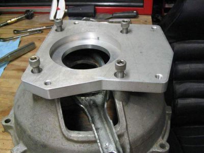
Right, here we go. Transmission adapter plate. The pic is for reference not the actual part but similar. piece needs a bore on one side centered in the 10 x 10 piece and the same i.d. size for the o.d nipple on the other side protruding out. I suck for words/description, hopefully the pic helps?

IMG_0848_zpsccaxzghw.jpe
 
If I were doing it, I'd do it on a mill, but that's just me. Second choice would be on a face plate. If it's possible, I'd drill the holes first to have something to bolt it to the face plate with.
 
You appear to have a straight gearbox adapter plate which mounts to a manual clutch bell housing.

Of primary importance is the ability to hold the input bearing and oil seal. Therefore, I would position a rough cut plate on a mill and bore both the large diameters with a boring tool at head position 0,0.

Of secondary importance is the ability to position the bearing precisely in the middle of the 4 hole pattern (shown with screws). This is critical to long bearing life. Without moving the plate, use the mill to step off the square bolt pattern.

Add the remaining tapped holes. Then the gearbox outer case can be mounted.

Trace around the gearbox case with a scribe, and bandsaw away the excess material from the plate as a final step.

The needs of the various components therefore determine the machining order, most important to least important.
 
steel plate clamped to alu, drill holes through steel into alu, flip alu for holes other side, tap alu holes, weld ring to the back of steel plate, ring the bigger the better, drill and bore steel to size od nipple, bolt alu to steel plate, make chips
ring could be piece of faced pipe or outer race of worn ball bearing
 
Pipe would be better. Bearings are hard although welding would probably soften it. Although I've cut them with a plasma cuter & there don't soften. After I cut part way through I smack them with a hammer to break them. Jaws would hold the softer pipe better.
 
Guess I'm missing something. All adapter plates we have machined here, do not have a counter bore?
Whats that for? The normal, is a bore, to register in the input shaft retainer. Or is it a foreign vehicle?
Just looking at the pic. that plate looks way too thick to deal with input shaft length / pilot bearing?
Just a sayin; I find this interesting... or is this a lathe operation only? If so I would locate and drill
and bolt the blank on a face plate bore the center, and locate on the bell housing centered then with a
couple dowels good to go. Drill and tap transmission bolts (backward) so they are studs & red loctite em in.
Allen cap screws through plate into bell housing.. Me, a mill and a boring head. sam


If I were doing it, I'd do it on a mill, but that's just me. Second choice would be on a face plate. If it's possible, I'd drill the holes first to have something to bolt it to the face plate with.
 
I'm with derf, mill 1st. choice, faceplate 2nd. More info needed.
 
Back
Top