Jet 13X40 Headstock alignment nightmare with Walter Meier.

Re: Jet 13X40 Headstock alignment nightmare with Walter Meier. Reply to Richard.

Mr. King:

My opinion expressed herein in my opinion alone and is based upon my unique experience with various field peronnel employed by the vendor and the statements I made below are the truth as I can recall.

Now, the 4th bolt was not behind the pulley!.... The bolt is in the electrical cabinet, a part of the bed, of course, oh dumb me.
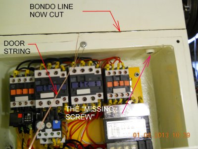
missing screw.JPG

Removed the door and hinges/frame on left side.

1) Then went to remove the pulley and with the frame off I could see there was nothing behind it.

2) The rear of the HS doesnt have a joint between the HS and the bed...it had been filled with bondo. Dumb me.

3) Then I measured top to crack front and struck me a line....dremel tool and cut the line.

Had it not been for your call to WM, I would not have found it.
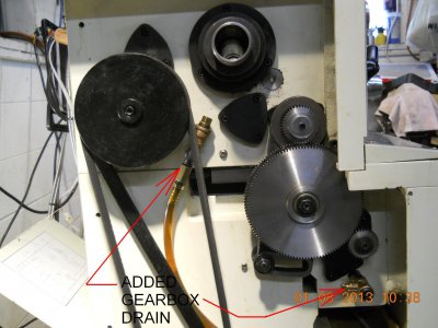

improvements.JPG

The belts supplied were short lived. As they failed they threw rubber all over the cabinet, like the "marbles" at a NASCAR track, so I cleaned all that up and have some fenner belts on the way from Grainger. It was a mess. The drain tubes I added make the oil changes a breeze. The stock drains are plugs. Ugh! whatta mess!

You can see that I have removed the door and the frame.

Mike
Remlap, AL

PS More to come. Many thanks to all contributors, and Mr. King who called JET. I can see the fat lady tuning up.

missing screw.JPG improvements.JPG
 
I use to say the only people who called me MR. King were my kid friends or the bill collectors. lol....Mike please call me Rich.
If the Jet is the only mechanical problem you have in your life, you are getting off pretty easy. Life's a ***** sometimes. Hopefully everyone reading about your Jet issues have been a learning from your experience. I am glad I could have helped and as I also tell people looking for a quick fix to things for a repairman ""It's not like we have a crystal ball". A lot of trial and error and being a detective to find and fix.
Have to thank Nelson for providing us this forum so we could all help you. Keep up the good work! Rich
 
These things are mechanical devices, and no magic is involved, but it sure can tax the patience of a rebuilder or repairman. And if it's new territory for you, it's understandable why it's even more frustrating. But perseverance pays, along with a little encouragement from friends. Keep pushing, and it will be over soon.
 
Re: Jet 13X40 Headstock alignment and Update model # GH-1340W

For those of you that have been following this thread, the following is an update to this issue. How do you get the text to wrap?


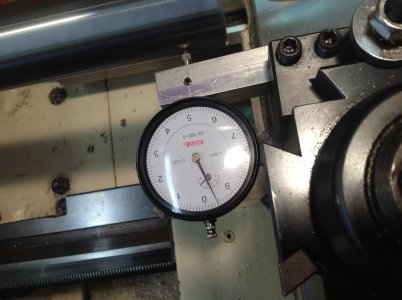
win52 022a.JPG

This is how I was able to get close, a secure mount for tenths DI. My prior useage was an SPI jointed-magnetic holder which was junk, at least for this application. Also, if you notice, the chuck has a commercially produced test bar closely ground and with a MT#5 end and a plain end. The MT is inserted in the spindle. There are other procedures w/o this bar which are described herein in prior posts by Mr. King. I suggest you research that explanation and approach.
The early parts of this thread reflects, among other issues, my own frustration with the distributor. At least in my thoughts, you get what you pay for, but not necessarily. So the last say 10 posts should be of primary interest to those with similar situations. Pay attention to the posts that show the location of the 4 HS bolts. Also as Richard King suggests, actually remove the cap screws and look for adequate clearance for the HS to move. I did not do this, which caused additional effort which I feel behooved to describe. Mirrors required.
Also I did find herein a thorough post that presents means of adjusting, analyzing tailstock alignment. Search "Simple Lathe Alignment Methods And Their Problems", I think by GaryC. Many topics are undertaken and it is well worth reading.
I suggest you not take anything herein as a guaranteed fact and satisfy yourself regarding appilcation to your unique situation.
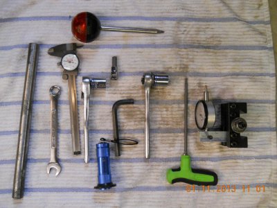
There exists (3) parts to contend with 1) the substructure or undercarraige, 2) the bed ways and finally 3) the headstock. The headstock bolts to the bed with a 1" pin and (4) cap screws which require a 10mm hex allen, torq drivers, 2-14mm end wrenchs, and a 1/2" pipe 14" long, 3/8" rachets for 16, 18 and 19mm sockets (for the gear set). Procure several pieces of 2" dia AL or a 1018, L18 or L17 bars. Also you might want a comfortable stool.


01-11-13 009a.JPG
Remove the left side access door, the motor cover and the electrical cover. Unplug the machine and devise a means to hold the relay cover open because you will have to power-on, power-off in the process. Be careful. There is 220 volts to the panel. It can kill you.

Cut the rear joint interface with the bed and the headstock.

The (4) HS cap screws I numbered, facing the lathe front #1 & 2, then #3 w/i the relay panel and finally #4 to the rear of chuck. Numbering clockwise from the front #1 under the chuck. After many hours of trial and error, the final procedure I selected was:
tighten all 4 finger tight++

start
with 2-14 mm end wrenches made your trial adjustment with the adjustment block (see photo) and tighten wrench firm. There will be some liaitance between the adjustment bolt head and the bed, loosen bolts and scrape to metal.
then:
tighten #1 & 3 to ~ 40ft-lbs slowly each half, then half.
then tighten #2 15 deg and watch DI, mine moved 0.0003" right facing rear.
then tighten #4 30 deg and watch DI, mine moved 0.0005" left.
tighten #1 with cheater bar ~ 80 ft lbs
tighten #3 with ratchet ~ 80 ft-lbs
tighten #2 15 deg and watch DI, slight movement, maybe a tenth,
then tighten #4 30 deg and watch DI, mine moved 0.0005" left.

This worked for me. Yours will be different.

read and weep,
Go to start

Once you are satisfied with the above and meas to DI, install gears. This will take 10~15 min after practice.
Remove your test bar and install chuck. (or not)
Install test piece, and cut collars, etc per R. Kings instructions herein. (I had several, including some 536 tube. None of the structural steels have machinability >40)

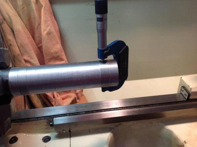
win52 026.jpg

Decision time. The end of bar toward TS should be 0.0002" larger in diameter. Wait, remeasure. Write it down in a log. Do not shortcut your note keeping. It will save you hours.

The JET 13X40 can be aligned to the specifications and w/i the Q/C supplied with your lathe. Do not expect the manf rep to be able or initiate the above procedure. (The rep told me "Mike, if you had told me I had a good lathe"). Just do it.

What actual time was involved? Once I found all 4 screws ~ 40 hrs. Remember I can be easily challenged.

Thanks to all that helped, Richard, John (without a pin) and Tony. Hope this helps a novice in the future or anyone that purchases a JET.

J M (Mike) H
Remlap AL

win52 022a.JPG 01-11-13 009a.JPG win52 026.jpg
 
Last edited:
Good for you, Mike. Sometimes messing with machinery can be frustrating, but as long as you accomplished your goal, and learned something along the way, you did as well as any of us.

I have to say this, though. You make me (and I'm sure a couple of others) cringe a bit when I see your pictures of your micrometer "clamped" upon your test bar.
 
Tony & Richard (somewhere in the south pacific),

FYI:
Hello. Took a piece of AL, 2.5" tubing, and made a single cut. Got same results, of course w/i my ability to measure. I have one more comment on this thread in about 2 mos.

Thanks again to ALL.

Mike

Picture 0031.JPG

Picture 0031.JPG
 
Back
Top