- Joined
- Sep 24, 2012
- Messages
- 495
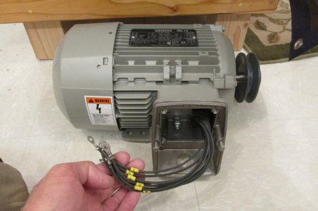
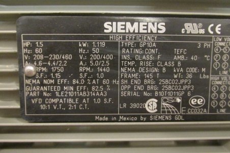
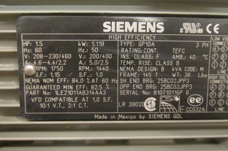
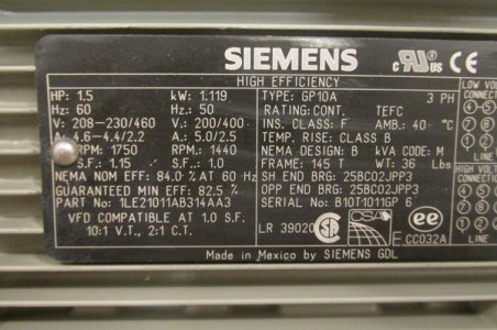
Here's yet another VFD question from yet another newbie. I think I'm probably even newbier than some of the other newbies here. For my Rivett Model No.4/504 lathe, I'm using 220V, single phase from the wall in my shop. The motor I got is a Siemens (made in Mexico), HP: 1.5, V: 208-230/460, 3-phase motor. For the VFD I picked up a Teco JNEV-201-H1.
Before posting this I read a dozen or more previous posts using "Teco JNEV-201" as search terms, because often whatever question I have has been dealt with already. Unfortunately I'm getting less confident rather than more confident about hooking everything up - so I wonder if I should call an electrician to wire things up for me.
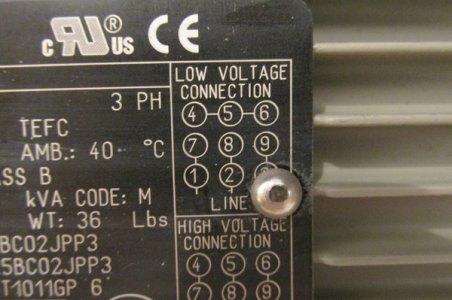
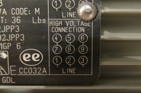
The motor has a pair of wiring diagrams on the plate that are confusing to me. One shows connections for low-voltage connections, and another diagram next to it shows connections for high-voltage connections, but it doesn't say "for 220, use this diagram, for 460, use the other diagram".....although that might be exactly what it means. Problem is, it's probably code that is widely known by electrically-savvy guys. I need a dummies-book version of instructions.
The other thing is on the VFD itself - the manual says to hook up the main power input to L1, L3(N), and PE. What it DOESN'T say is "hook up the hot to the (whatever), the neutral to the (whatever) and the ground to the (whatever)". Why go to the trouble of writing a manual when you just leave me guessing what goes where?
Another question from reading the previous posts here is: should I install a red emergency button? I noticed a few guys mentioning that.
Should I hire an electrician to do the electrical hookup for me?
Thanks,
...Doug


