I need some advice for powering a mill

The biggest thing with VFD is to ensure there is NOTHING between the VFD and the motor. No switches, branches, nothing. Suddenly switching the motor out of circuit can destroy a VFD. Just wire the switches to the VFD inputs. Then 3 wires motor-VFD. I also like grounding the body of the machine and motor, it's a safety ground and should carry no current unless there is a fault, and the breaker handles the rest if there is. I used a 4 conductor cable and ran the ground back to the VFD which is tied to the house ground.

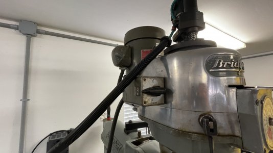
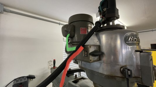
The way the machine is currently wired, it takes main into a junction box on the back. That feeds the 3-position Forward-Off-Reverse switch, marked in red.

The switch feeds the motor, marked in green.

If I understand you, I’m to wire the green directly to the VFD, omitting the 3-position switch?

My plan was to wire from the VFD to the junction box, and call it a day. That’ll blow the VFD?
IMG_4782.jpegIMG_4785.jpegIMG_4781.jpegIMG_4783.jpeg
 
i built my own phase converter, and upon my research in that regard, I sized the motor for the phase converter at least double the max load it will ever see. my converter is a 3 hp, and my mill is 1/2 hp, and the lathe is 3/4 hp. it works great.
 
VFD's are nice, but you will have to do some wiring for each machine. I think the RPC is the easiest and most economical way to go. Your mill is already variable speed, so you're not gaining that benefit from a VFD as you would with a step pulley machine. For my last go-around, I went with a Phase Perfect. It's more expensive than an RPC, but it's quiet and provides stable voltage on the three legs. I am very pleased with it.
 
VFD's - you wire the machine with a VFD then you can plug it into any 220v socket.

RPC - You bring home a new machine and can plug it in right away without having to do any alterations to the machine wiring.

I have both.
 
I've never used a VFD but have a (home built) rotary phase converter. I like using the electrical control on the machine.
The idler motor used as a RPC needs to be at least twice the hp of the driven machine. More if the driven machine is geared, meaning higher current @ start. Likely for your applications you should have a 5HP idler motor.
If you buy or make a rotary phase converter it can provide for both machines you now have and any added machines in the future as long as they don't exceed the RPC. I managed to get given a 3 phase cold saw, so if you add something unexpected in the future just pug it in to your RPC circuit and go. Not the case if you use VFDs. You will have to get another VFD for each new tool.
 
I just finished wiring a Willis variable speed mill to a VFD. The motor is 3hp and the VFD is rated for 5hp. The motor wires go directly to the VFD. The factory drum switch is wired to the inputs of the drive to control on-off and direction of rotation. Remove the jumper wires from the switch and use a meter to ring out the terminals to find out which contacts are made for fwd and rev.

I have the VFD set to 60hz and leave it there.
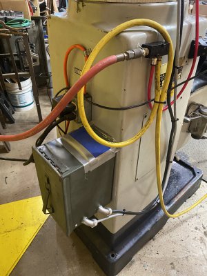
I installed the VFD on the back of the mill in a vented ammo can. The black cable runs to the motor and the gray cable goes to the drum switch.

IMG_2290.jpeg
 
Last edited:
Phase converter - love my Phase Perfect (though I used an RPC for about 35 years and only replaced it because I bought a machine that had a larger motor than the rating of the RPC). My idler motor was a 5hp and it had no trouble starting the 5hp air compressor (which has a pressure unloaded), but the lathe would only give one or two starts on the 5hp setting before tripping the RPC overloads. I just ran the lathe on the 3 hp setting - to occasionally run on the high speed I’d start on the low speed and switch up.

You could certainly build yourself an RPC with the extra motor you have (a mill is easy starting), then if you had issues down the road simply upgrade that motor (after you’d already proven out everything else worked fine).

Obviously there are going to be people who support about every possible option to power a machine. It depends on your situation, I have ~10 machines, so I’m going to favour a phase converter. I have a couple machines running on single phase via VFDs (because of my shop layout), my experience is that the VFD is not a game changer, it is a convenience - one that might make sense in your application. Only you can decide.

Loved your shop tour pictures.
 
Last edited:
The way the machine is currently wired, it takes main into a junction box on the back. That feeds the 3-position Forward-Off-Reverse switch, marked in red.

The switch feeds the motor, marked in green.

If I understand you, I’m to wire the green directly to the VFD, omitting the 3-position switch?

My plan was to wire from the VFD to the junction box, and call it a day. That’ll blow the VFD?
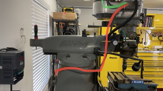
View attachment 478198


The junction box on the back of the machine is fine, and can serve as a ground point. If you never move the switch, it's fine. I didn't want to risk it. I removed it entirely and put a low voltage control box I built there. Then wired from motor to VFD. If you want to keep the switch, you need to remove it from that circuit and wire it to the VFD control inputs. What you can not do, is use it as a rev-off-on switch as is. If it's on or rev, the VFD can run the motor. Till you flip it. Then the VFD might or might not let the magic smoke out. It might just error out, if you're lucky.

Try to think of the VFD as a motor controller, not as a phase converter. A phase converter, static or rotary, WILL work the way you show the wiring. For what you are doing, both are fine, and you wouldn't be using the VFD's big advantage of speed control. They do change how you run the wiring though.
 
IMG_2251.jpeg

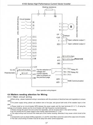
This is the wiring terminal layout of my drive. R S and T are the incoming power. My drive is for single phase input so terminal T is blocked from the factory. U V and W connect directly to the motor. DI1 goes to Fwd contact a DI2 goes to Rev contact on the drum switch. The Com terminal feeds power to both sides of the drum switch. Those are the only connections I used other than the ground. I am not using a brake resistor since I’m used to using the hand brake on the mill. I initially tried using the decel feature but if I tried setting it to stop fairly quickly, the drive faulted and if I hit the hand brake while it was decelerating it would take off running again when I let off the brake because there was still current going to the motor until the decel time expired. I found there is what’s called “Free stop” in the settings which cuts power to the motor when the switch is turned off. It now coasts to a stop like I’m used to and I use the brake to stop the spindle.
 
Last edited:
If I understand you, I’m to wire the green directly to the VFD, omitting the 3-position switch?

My plan was to wire from the VFD to the junction box, and call it a day. That’ll blow the VFD?
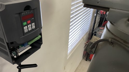
Correct, that will kill the VFD. When a switch opens and closes the voltage spikes and VFDs can't handle that. There can be nothing between the VFD output and the motor...no switches, etc. Any switches need to be wired to the control inputs on the VFD.

For a setup like yours, a rotary phase converter or a Phase Perfect setup makes a lot of sense. A 3hp RPC would work for your current machines, but the price jump to a 5hp unit isn't much ($50) so that's what I would look at...just in case you get something slightly bigger. I spent a lot of time researching RPCs and narrowed it down to North America Rotary and American Rotary and found the two are nearly identical in features and warranty, but North America is a bit less expensive. I've got machines up to 5hp, so I went with the PL-7 and it's been fantastic...powers my 5hp shaper with no issues.

For around the price of two decent VFDs you can get a 5hp RPC. I bought mine on Amazon because we've got a Prime account (points) and the shipping was free...they've got an Amazon store.

 
Back
Top