

-
Welcome back Guest! Did you know you can mentor other members here at H-M? If not, please check out our Relaunch of Hobby Machinist Mentoring Program!
- Forums
- SPECIFIC MANUFACTURERS OF MACHINE TOOLS
- BOXFORD, MYFORD, DENFORD VICEROY, EMCO & UNIMAT MACHINES
You are using an out of date browser. It may not display this or other websites correctly.
You should upgrade or use an alternative browser.
You should upgrade or use an alternative browser.
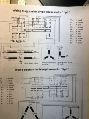
I am looking for help on Emcomat 8.4 Mill Head wiring
- Thread starter OmarA
- Start date

- Joined
- Apr 30, 2015
- Messages
- 11,328
Three phase or single phase motor? Are you able to scan or photograph pages from the manual?
The information should be there, we can help you interpret it
-Mark
The information should be there, we can help you interpret it
-Mark
Hi Mark thanks for replying…. It is single phase 120vac.Three phase or single phase motor? Are you able to scan or photograph pages from the manual?
The information should be there, we can help you interpret it
-Mark
Attachments
- Joined
- Apr 30, 2015
- Messages
- 11,328
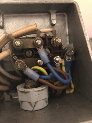
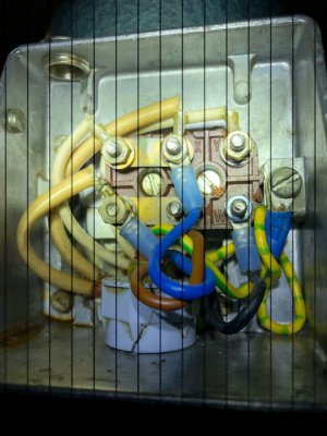
OK good. Now, do another close shot of the motor as in post 1, only this time move the wires so as to get a
better view of the terminal block behind
-M
better view of the terminal block behind
-M
Last edited:
- Joined
- Apr 30, 2015
- Messages
- 11,328
I see the wires are connected in that picture- did it not work in that configuration?
I'm thinking it looks correct except for the black wire which should move up to the upper right post
PS this thread should be under "all about electrical" or the Emco section
I'm thinking it looks correct except for the black wire which should move up to the upper right post
PS this thread should be under "all about electrical" or the Emco section
- Joined
- Apr 30, 2015
- Messages
- 11,328
Any luck?
-M
-M
- Joined
- Apr 30, 2015
- Messages
- 11,328
We don't know if the wires from the motor to the terminals are in their original positions or not- so the letter designations may not match up.
From the diagram the black wire must be connected and not hanging free; likewise, the single wire on the upper right hand post should be connected
to one of the three control wires so it stands to reason the black might go there. We just want to see rotation even if the direction is reversed.
Try it and see, it should run. The direction can be inverted if necessary by swapping two leads.
Last edited: