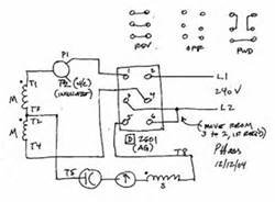
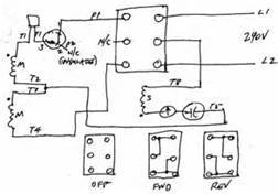
Guys on a previous post I had ask bout the purpose of having reverse on the lathe and thanks for all the responses to that question.I am going to go back with the drum switch since its what the lathe had on it.On another post here in this section I had ask bout how to wire this motor due to no motor tag stating what voltage 120/240 or hp the motor is.On the wiring which is short is P1,P2 then T2,T3,T4,T5,T8 and I was given a diagram on what motor leads go togeather for CCW/CW so thanks for that information.
The previous owner had it wired for 220(guessing looking at the cord cap) with a Rev/Stop/For,and a 3 position toggle switch which I cannot figure out what its for.
http://www.naemotors.com/wp-content/uploads/2011/08/Single-Phase1.pdf
On the diagram my motor leads match up with diagram on the first page bottom right 115v or 208-220v Low Voltage. Drum Switch:On the left side is 1,3,5 then on the right is 2,4,6 The previous owner had the power coming in on #2 and on #6 with wires on #4.There is no wires on #1,#3,wire was on #5 if any of this helps.
Can someone provide information on how to wire all this togeather 1)Motor,2)Drum Switch,3) Toggle Switch (3 position) do I need it?If you have a wiring diagram of this could you provide it as well and any how to's for this simple minded person.Thanks---kroll


