
Your numbers didn't seem right, so I just double checked your math, your life calculation is incorrect, I get 13,324 hours, which is much better. You are still below the recommended loading to prevent skidding, but not as much as I thought when looking at your number, so that might work ok provided you took into account all the forces on it. If your loading numbers are correct, a 607 bearing would be better, that would put you a bit over the 10% loading recommendation.

-
Welcome back Guest! Did you know you can mentor other members here at H-M? If not, please check out our Relaunch of Hobby Machinist Mentoring Program!
You are using an out of date browser. It may not display this or other websites correctly.
You should upgrade or use an alternative browser.
You should upgrade or use an alternative browser.
How to find the axial load rating of a deep grove ball bearing.
- Thread starter Iron Filing
- Start date
- Joined
- Feb 25, 2023
- Messages
- 36
Thanks for double checking my math. As I'd rather not make mistakes twice, where did I go wrong?
Offset about 27 minutes.
The cups are indeed driven off of one shaft. I could do a pulley system with the motor, but I wanted to go for direct drive. I don't really see a reason to add more parts, such as a pulley.You need to factor in the load from what is driving this too, do you have a pulley and some sort of belt? It looks like the rotating cups are driven off of the center shaft?
Okay, that's a bit of a new topic to me. How would I make a bearing float axially? I'll happily read anything you point me to, I'm just a bit lost on how this is achieved.Most of your axial load will be taken up by one bearing, and you usually want one bearing floating axially so that the shaft can expand from heat.
OkayFor what you are doing that might be minimal, but not knowing the design, it might not be either. In either case, it is usually a good idea to have a bearing that floats axially. You can also have bearings of different sizes at each end, they do not need to be identical, the important thing is that they are sized correctly for the loads on them.
Understood.I would not use an aluminum shaft for this, it has a much lower rigidity than steel and you could cause more vibration problems by doing that. Nothing is ever perfectly balanced, so your device will have some imbalance in it, and then the mixture would too. That imbalance is going to try and bend the shaft, so stiffer is better.
The best I could find in my searches was this gentleman's video:I couldn't find an O&M for these mixers, I am curious how the commercial units are built internally.
In the formula you posted,Thanks for double checking my math. As I'd rather not make mistakes twice, where did I go wrong?
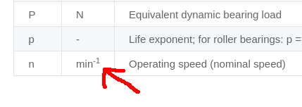
(constant / ( rpm to the -1) * (Cr / P ) ** ball bearing life exponent.
(16666/(1600**−1))*(3300/304)**3 == 34109270324.6 hours.
the bold part should just be the rpm, when you calculated it that way, you were multiplying the 16,666 x 1600 when you should be dividing.
you don't need to use a pulley, I just mentioned it in case that was what you were using.The cups are indeed driven off of one shaft. I could do a pulley system with the motor, but I wanted to go for direct drive. I don't really see a reason to add more parts, such as a pulley.
Here is a link to a page that shows different bearing arrangements. The top one on the left has the bearing on the left side of the shaft fixed to the housing, the bearing on the right side is able to float axially by not have anything locking the outer ring in place. That allows expansion of the shaft during use, and also you don't need to worry about tolerance stackup since that bearing can move to where it needs to be. The easiest way to do that is to fix the bearing on the shaft, and then have a housing without a shoulder or cap that prevents movement.Okay, that's a bit of a new topic to me. How would I make a bearing float axially? I'll happily read anything you point me to, I'm just a bit lost on how this is achieved.
Design of bearing arrangements | Schaeffler medias
I came across this company that has a cross section of a mixer, they use a drive belt/pulley on the spindle, but I don't see why a direct drive wouldn't work if you could find a motor of the correct speed. I have a better idea of how these work now.

China High Quality Solder Paste Mixer SMT Machine Suppliers & Manufacturers - Factory Direct Price - ETON
Welcome to buy high quality high quality solder paste mixer smt machine at competitive price from professional high quality solder paste mixer smt machine manufacturers and suppliers in China here. For more details, contact our factory.
- Joined
- Feb 25, 2023
- Messages
- 36
I'm not going to argue with you. You know more than me. But it *really* looks like that's what they put in their formula (picture attached). Maybe we should say something to them?In the formula you posted,
(constant / ( rpm to the -1) * (Cr / P ) ** ball bearing life exponent.
(16666/(1600**−1))*(3300/304)**3 == 34109270324.6 hours.
the bold part should just be the rpm, when you calculated it that way, you were multiplying the 16,666 x 1600 when you should be dividing.
I'll read the fine material you linked and get back to you.
Attachments
- Joined
- Feb 25, 2023
- Messages
- 36
Here is a link to a page that shows different bearing arrangements. The top one on the left has the bearing on the left side of the shaft fixed to the housing, the bearing on the right side is able to float axially by not have anything locking the outer ring in place. That allows expansion of the shaft during use, and also you don't need to worry about tolerance stackup since that bearing can move to where it needs to be. The easiest way to do that is to fix the bearing on the shaft, and then have a housing without a shoulder or cap that prevents movement.
Ah, yes. Though I did not know the technical term, I was thinking that I should float the bearing anyway. Though their recommendation, that you use a relaxed fit such as h6, was something I had not considered.
Now you were saying that I should have one bearing take the axial load and one the radial load. I was thinking that the top bearing should be a floating radial load bearing ball bearing and the bottom one should take the axial load, which means it should be a roller bearing IMHO. What do you think?
Stick with ball bearings for this. A ball bearing can handle axial loads, and you will have radial loads at both locations, so the bottom bearing has to do both. Both housings would get the same fit, the fit on the shaft is tighter to prevent the inner ring from spinning, but the housing fit is slightly loose with an H6 or H7 fit so you can install it, and so you don’t take out too much clearance in the bearing by compressing the outer ring. If you have tight fits on the inner and outer rings, you can remove all the clearance in the bearing and cause it to lock up, that would be really bad. The bottom bearing should have a shoulder and a bearing cap that will secure the outer ring in place, and the upper bearing will have enough clearance with the housing for the outer ring to slide axially as needed.