How to check whether two surfaces are in good contact ?

compact8

Registered
Registered
Joined
Oct 13, 2012
Messages
324
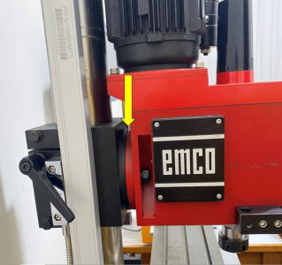
My Emco FB2 mill is out-of-tram along the Y axis by 0.05 mm over a distance of 150mm and I am planning to make a wedge shim between the head and the vertical slide block ( if that's the correct term ) to correct it. The photo shows the location of the shim.

I have already got some idea on how to machine the shime but how can I check whether the shim is in good contact with the metal surfaces on both sides ? The head is secured to the slide block only by two bolts, one on each side. It is possible that the shim is not machined well leaving gaps on the upper or lower sides. That can severly affect the rigidity.

I am thinking about using engineering blue but I will not be able to rotate the head like sliding a piece of metal being checked over a flat reference surface because once the bolts are loosen, the weight of the head will tilt it. Will it be sufficient to just tighten the bolts and then take it apart to check the colorization of the contact surfaces ? Will appreciate some advices.
 

Attachments

  • Capture.JPG
    Capture.JPG
    76.5 KB · Views: 27
One method that was (maybe still is, I don't know) recommended to check whether a part was firmly seated in a vise prior to machining was to put a slip of cigarette paper under each corner. A gentle tug on each slip after the vise was tightened down would tell if the part was seated at all corners. To within the thickness of the cigarette paper anyway, which is typically 0.001".
 
I would make an experiment out if it and put some bluing or whatever you are going to use on one side of two pieces of metal and
it it in the vise and see what happens.
 
Or maybe shim the column to tram it in? My old Grizzly round column mill was trammed in the Y-axis by shimming the column.

Bruce
 
I would not shim your mill there.
If it is out on your y axis I would remove and stone the two mating surfaces of the column. The column has your Z axis "runway" on it.
Motor and head.
Install the column and retest for error.
Remember if your headstock has a z axis brake to try your tramming measurements with the lock on as well as off to see what variation this might cause.
I prefer to use plastic shim stock over metal.
All the tram measurement was done with the Z axis and quill locked.

The column is already tilting backward but the amount is small ( 0.015 mm over 90 mm ) so I just leave it. If I shim the column support, which is definitely easier, the column will tilt backward even more. That will cause the Y position to shift more significantly if the Z position is changed so I am afraid thats not an option.
 
Last edited:
Shim the column to correct the error.
This would mean a partial peice
 
There appears to be some confusion between the column tram and head-to-column alignment on the part of some folks here. Both need to be good for best accuracy, but your problem appears to be mostly due to an alignment problem between the column and head since you're concerned about shift of the Y axis position as you change Z. BTW, rotation of the head can result in shift of the X axis vs. Z as well so that's something to keep in mind if you do loosen up the head to do something.

I've seen accounts of owners placing shims between the head and column to address head-to-column alignment problems, but none have reported rigidity issues as a result of that. I'd suggest taking the simplest approach and evaluating the result. If it's acceptable, you're good. If not, well, it gets more "interesting".
 
Watch out for the piece of metal showing curves because of unequal temperatures on both "flat" sides of the piece. It takes little difference in temperatures, even with hands, to move it from it's previous curves or flatness. It can drive you crazy until all the parts of all the metals involved are allowed to sit together for some time so nothing can keep changing it. It takes some thinking about it, none of this is usual things until we deal with understanding what is happening. Something like a cold floor and a hot cover on the roof in the shop can do it...
 
Last edited:
Take it apart, clean it out and ink it up on mating surfaces.

Assemble with okts snug then wiggle head.

Take back apart and see if it is mating properly.

Maybe some scraping is needed here to optimize the fit.

Sent from my SM-G781V using Tapatalk
 
Back
Top