How to build a controller for a DC motor?

mac1911

Registered
Registered
Joined
Sep 29, 2022
Messages
739
In my hunt for a hunk of round cast iron for a project I came across a free tread mill.
I have all the electrical components and controls , but using the control panel would take up a good amount if room ( printed flexible circuit board)
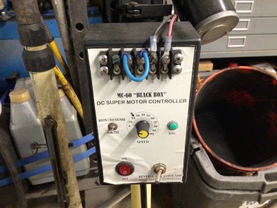
I cant see it being overly hard to find a generic control unit. I just dont know where to look.
This is the motor. I was thinking of installing it on my belt driven lathe to have a little more speed control.
I have 4 speeds with the belt configurations. Was thinking of setting up the fastest speed belt set up and I could turn the speed down as needed? 3EA07886-62F9-45F1-9BA7-5F2DCFFAA701.jpeg3EA07886-62F9-45F1-9BA7-5F2DCFFAA701.jpeg
 
show us a picture of the control panel and the power supply/ controller itself, that will help us give you some better advice
 
I would like to have reverse option also.
Theres the reverse switch on the lathe already ?

image.jpgimage.jpg
 
Years ago I got the bug to do a treadmill power conversion and found a good motor and at that time a controller on eBay. It was based on a MC-60 control board and they put it in a box with switches and controls. I ended up using it on my powder coat shaker with a 24vdc motor. I looked and didn’t see one like it but just did a quick search.
 

Attachments

  • IMG_0600.jpeg
    IMG_0600.jpeg
    487.7 KB · Views: 6
I replaced the 1 hp a.c. motor on my Grizzly G0602 with a 2.5 hp brushed d.c. motor. I built my own controller from scratch. Specifically, aside from variable speed, I was looking for enhanced low speed operation. My first try was a Variac feeding a full wave bridge which provided variable speed but very poor low speed torque. I tried a couple of off the shelf solutions that didn't pan out so I just designed my own controller. The idea was to use simple readily available components.

I incorporated a full wave bridge with a 4,000 mfd filter which provides a no load voltage of 176 volts and 120 volts at full load My design is based on PWM using a MOSFET transistor as the controlling element. Low end response was still less than I was expecting. I realized that the poor low end performance could be improved by adding feedback to the circuit. A home built encoder provides speed feedback and when the motor starts to slow down due to increased load, the circuitry increases the pulse width to increase the torque to maintain the selected speed.

The no load maximum speed is about 5,700 rpm but I limited my maximum speed to 4,500 rpm as the motor is rated for 4,300 rpm @130 volts d.c. . I have usable torque to below 40 rpm for a 110:1 useful speed range. I retained the original pulley setup so my overall spindle speed is from around 3 rpm to over 5,000 rpm. For virtually all my lathe work I use the medium low pulley setting which gives me a speed range of 6 rpm to 800 rpm. When threading, I can dial down to zero rpm as I approach the end of my thread which allows me to stop at the same position on each pass. This makes threading to a shoulder worry free, even for metric threads.
 
Perhaps I should have taken electric shop instead of all "General Metals"; I must say that I am a bit envious of the talent involved to come up with such as you describe ---
 
I replaced the 1 hp a.c. motor on my Grizzly G0602 with a 2.5 hp brushed d.c. motor. I built my own controller from scratch. Specifically, aside from variable speed, I was looking for enhanced low speed operation. My first try was a Variac feeding a full wave bridge which provided variable speed but very poor low speed torque. I tried a couple of off the shelf solutions that didn't pan out so I just designed my own controller. The idea was to use simple readily available components.

I incorporated a full wave bridge with a 4,000 mfd filter which provides a no load voltage of 176 volts and 120 volts at full load My design is based on PWM using a MOSFET transistor as the controlling element. Low end response was still less than I was expecting. I realized that the poor low end performance could be improved by adding feedback to the circuit. A home built encoder provides speed feedback and when the motor starts to slow down due to increased load, the circuitry increases the pulse width to increase the torque to maintain the selected speed.

The no load maximum speed is about 5,700 rpm but I limited my maximum speed to 4,500 rpm as the motor is rated for 4,300 rpm @130 volts d.c. . I have usable torque to below 40 rpm for a 110:1 useful speed range. I retained the original pulley setup so my overall spindle speed is from around 3 rpm to over 5,000 rpm. For virtually all my lathe work I use the medium low pulley setting which gives me a speed range of 6 rpm to 800 rpm. When threading, I can dial down to zero rpm as I approach the end of my thread which allows me to stop at the same position on each pass. This makes threading to a shoulder worry free, even for metric threads.
We used to have a U pick it Electronics store locally. You could walk in and find someone willing to help. Closed down before covid
 
I picked up a controller off Amazon the run my little CNC mill with a similar motor. It doesn't take up much room.

uniquegoods AC 110V 120V 220V 230V 10000W High Power SCR Motor Speed Controller​

 
I've built a couple of controllers using the ideas from 'The Aussie Shed' on youtube. One for a variable speed motor for a drill press, the other to control the DC motor in my 7x lathe when I blew the stock controller. They work OK, and aren't too difficult to put together.
 
Back
Top