How Much Chatter Is Acceptable?

It also may be out of tram.

I see a step in the surface, either the cutter depth moved or out of tram.

Place a chunk of handy scrap in vise, des not matter but needs to be say 4 times the width of your end mill.

Locate and install the largest end mill you have.

Program or manually make it. Flat by cutting across right to left, then moving almost full width of end mill and go back.

Repeat until finished.

Should NOT have any ridges.

If not, repeat but now go front to back on cutt and shift left or right away from the material.

There are tools for adjusting tram, this test shows results.

Sent from my SM-G781V using Tapatalk
 
If thats your first part, you certainly seem to have a knack for this type of thing…
 
It also may be out of tram.

I see a step in the surface, either the cutter depth moved or out of tram.

Place a chunk of handy scrap in vise, des not matter but needs to be say 4 times the width of your end mill.

Locate and install the largest end mill you have.

Program or manually make it. Flat by cutting across right to left, then moving almost full width of end mill and go back.

Repeat until finished.

Should NOT have any ridges.

If not, repeat but now go front to back on cutt and shift left or right away from the material.

There are tools for adjusting tram, this test shows results.

Sent from my SM-G781V using Tapatalk
Thanks. I did tram the mill using a tool that extends about 8" out from the spindle. I got it to less than .005 but I will surely check it again. You mentioned using a hunk of metal 4 times the width of the mill. I'm not sure what you meant?

Thanks... Richard
 
Chatter can be caused by taking a conventional cut when a climb cut is required. Other than that cutter comp can be beneficial for roughing and finish passes. CAM is just a starting point. My .02
 
@Metalshop

Looks nice to me! I have a PM CNC machine, but not the quality of yours. I have limited experience at all of this, but I think chatter can have multiple causes and they can probably interact. Many times I see chatter like the side of your part when doing climb cuts and find that if I run the last pass backwards (normal cut) with a small depth cut that it will clean up somewhat. Sometimes in soft material like aluminum the surface just smears and looks worst!

I am going to assume that you were doing a climb cut and this is the resulting surface. Then we might ask if this is the spacing between the flute touches. So you could do this calculation (and probably did when you were figuring out your feed rate) and would find that it is not the case even if only one edge of the cutter were hitting. Example: You say the thickness of the work is 0.75". From the photo we might "guess" that there are about 10 chatter marks per thickness, but this estimate is difficult from the photo. This yields ~ 0.075"/chatter mark. But at the 3000 RPM and 7 inches per minute would mean ~430 rev per inch or ~ 0.0025"/ revolution. So even if only one flute were cutting it would not leave chatter marks so far apart.

I like to think of chatter as vibration (modulation) of the cutter-work distance. Hence, this maybe related to a resonance in the distance between the head and the table (cutter and the work surface). Due to the heavy mass of the machine, the resonance vibrations of the machine are probably much lower frequency than the cutter touch frequency. Hence, changing the feed rate or the cutter rotational rate may change the resonance occurring and decrease or make the chatter worst. The bigger and heavier ($$$) the machine the lower the frequencies and probably the amplitudes of the resonances.... and so less vibration.. and related chatter.

In my machine, I can actually hear the resonances (noise) of the tables vibrating at low speeds and I think this has a lot to do with the finite motion of each step of the stepper motor effectively jerking the table position. If I speed up the travel velocity a lot of this noise simply goes a way. So this may also say something about the back lash as it is a form of looseness of the table/work. When the cutter flute hits the work, especially in a climb cut, it pushes off the work a bit and backlash could come into play. This could excite one of the many possible machine resonances. Hence, the first think we try to get rid of chatter is the speeds and feeds!

PS. I recently did a similar side cut, but on a curved profile along a double stack of 1/2" thick Aluminum (1" total thickness). So both X and Y were moving. I GUESSED my feed and speed and used a climb cut, ~800 rpm, ~20 in/min., 0.015" depth of step over cut per pass, 3/8" diameter 4 flute HSS cutter. The cutter flute height just barely covered the 1" total thickness of the two pieces of Al. If all 4 flutes were hitting then this would have been a rev. cut depth of ~ 0.008". If only one flute was hitting then it would have been 0.032". I was not particularly trying to make a smooth surface! Here is a picture, but I suspect that I scratched up the surface a bit either by use or with sand paper taking the edge burrs off. If you magnify the pictures you can see the cut and chatter on the curved surface.

Dave L.
 

Attachments

  • 20230102_173459.jpg
    20230102_173459.jpg
    346.8 KB · Views: 57
  • 20230102_173239.jpg
    20230102_173239.jpg
    323.3 KB · Views: 63
Thanks for the kind words & encouragement.... Very much appreciated :). I really have no reference point to know exactly what these parts should look like.

In response to your questions:

Rodneyk: I sadly purchased the last CNC conversion kit from Heavy Metal CNC. Trust me, you should be glad that you did NOT. The kit was a total mess. Here are the details and hassles of my conversion: https://forum.drdflo.com/t/another-pm-833tv-conversion/307
The good news is that Dave Clements from Arizona CNC kits is just about ready to release a kit for the PM-833. His kits are of far better quality. here is a quick video about the new kit:
Dave really knows the fine details of these machines. If you do this conversion, I made dozens of 3D printed parts for this conversion and I would be happy to share them with you. Please feel free to reach out.

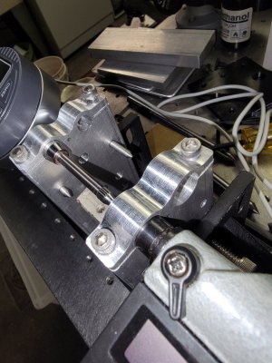
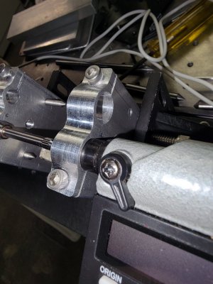
Nutfarmer: I don't think the gentlemen on the Fusion 360 CAM forum was putting down the part in any way. He was very helpful with my toolpaths. He noticed the surface finish and was concerned that my spindle bearings may be bad. I don't think he has any experience with smaller mills. Thanks for your complements! I have included an image of the mill with this part in the vice.

T Bredehoft: I never touched a milling machine in my life before converting this machine. I spent most of my life doing woodworking as a hobby. Two years ago, I gave up my woodworking due to shoulder issues (4 surgeries in the past 40 years). I watched a YouTube video of a CNC conversion and thought.... Great....Let those stepper motors do the work so my shoulders don't have to... I spent the last two years researching and building this conversion and learning CAD and G-Code. Thanks for you compliments.

7milesup: The contour of the part was machined with a 3/8" end mill. I was thinking of using a 1/2" end mill in the future to possibly decrease chatter. The online class I am following used a 1/2" end mill, I just happened to have a 3/8 on hand.

Again... thanks for all your nice words. The Titans Of CNC building block series is a free online class. I think it has been extremely helpful for someone starting from nothing. They have several other classes as well. The only challenge I have is that it is aimed at teaching someone to become an apprentice machinist at a large shop. For this reason, all the speeds and feeds are targeted at large production machines. I am doing my best to use the GWizard calculator to adjust my speeds and feeds for a 2HP machine.

View attachment 431909


Here is my second part. Just finished it yesterday.
View attachment 431910


Thanks again... Richard


That is a really nice shop you have there Richard! I love the looks of the floor.
 
Thanks. I did tram the mill using a tool that extends about 8" out from the spindle. I got it to less than .005 but I will surely check it again. You mentioned using a hunk of metal 4 times the width of the mill. I'm not sure what you meant?

Thanks... Richard
If you are using a 1/2 inch end mill then something about 2 inches wide.

0.005 is a bit off, may be pat of it.

Sent from my SM-G781V using Tapatalk
 
Thanks again... Richard


Thanks! I was waiting for the Arizona kit but they never responded to a query I sent them last month so I figured it was not happening any time soon. If you look at the comments on that video you will see a comment left by me (ToBeeOrNotToBe - I raise bees too) 3 months ago. I hope they make the kit available soon...
I would love to see your 3d printed parts. I have a number of 3d printers available that I prototype on...
 
Back
Top