- Joined
- Nov 4, 2011
- Messages
- 124
Here are a few more pics just in case someone follows me with the same problem. Don't know why the pics are on their side. The R8 spindle is carried in a sleeve with a bearing at the top and one at the bottom. Here it is just out of the mill head.
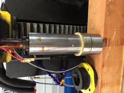
Pulling the spindle requires loosening the preload nuts - those suckers were TIGHT - I supported the spindle in my lathe with a center in the tailstock so I could focus on the nuts.
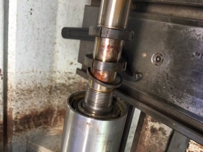
I think this device is called a bearing separator - the opposite side of the two plates are beveled to a fairly sharp edge. As you can see from the 1st pic above there was not enough room to get any sort of puller between the spindle and sleeve. Here it has already come most of the way out.
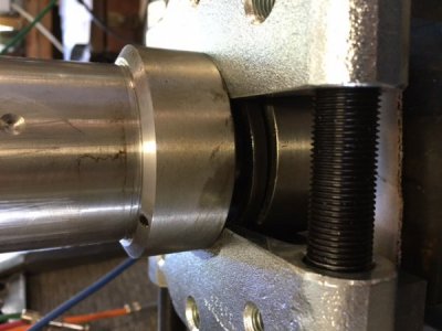
Once the spindle was out it was easy to pop out the bearings. The larger race had space below it - I was able to get in there with puller jaws and get it part way up - then they refused to grab any more. (I don't own one of those nifty pullers with a cup that screws down over the puller jaw and forces/holds them outwards. That would have been really helpful.) Anyway, now I had an even bigger gap under the race. I cut two pieces of 1/4" thick aluminum, long enough to drop down through the largest diameter and then slide outward until they looked like this. Invert it (again over a ring sized to support the sleeve and give the race somewhere to go) and knocked the race out the rest of the way from above.
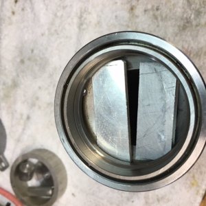
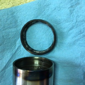
It was the other end that was more difficult. Here you can see a little heat got to the sleeve in the process but it is still nice and round and cleaned up nicely.

Pulling the spindle requires loosening the preload nuts - those suckers were TIGHT - I supported the spindle in my lathe with a center in the tailstock so I could focus on the nuts.

I think this device is called a bearing separator - the opposite side of the two plates are beveled to a fairly sharp edge. As you can see from the 1st pic above there was not enough room to get any sort of puller between the spindle and sleeve. Here it has already come most of the way out.

Once the spindle was out it was easy to pop out the bearings. The larger race had space below it - I was able to get in there with puller jaws and get it part way up - then they refused to grab any more. (I don't own one of those nifty pullers with a cup that screws down over the puller jaw and forces/holds them outwards. That would have been really helpful.) Anyway, now I had an even bigger gap under the race. I cut two pieces of 1/4" thick aluminum, long enough to drop down through the largest diameter and then slide outward until they looked like this. Invert it (again over a ring sized to support the sleeve and give the race somewhere to go) and knocked the race out the rest of the way from above.

It was the other end that was more difficult. Here you can see a little heat got to the sleeve in the process but it is still nice and round and cleaned up nicely.


